
Introduction
Cameras are a vital technology in scientific imaging, working as an interface between light and a digital image. There are a number of steps involved to convert photons of signal from your sample to the image you see on your computer monitor, each step has variables and factors that can change the ways in which images are generated. Bit depth is one of these variables, by understanding how it can affect your images and improve your experiments, you can perform more efficient and informed imaging research. The journey from light to an image is displayed in Fig.1:
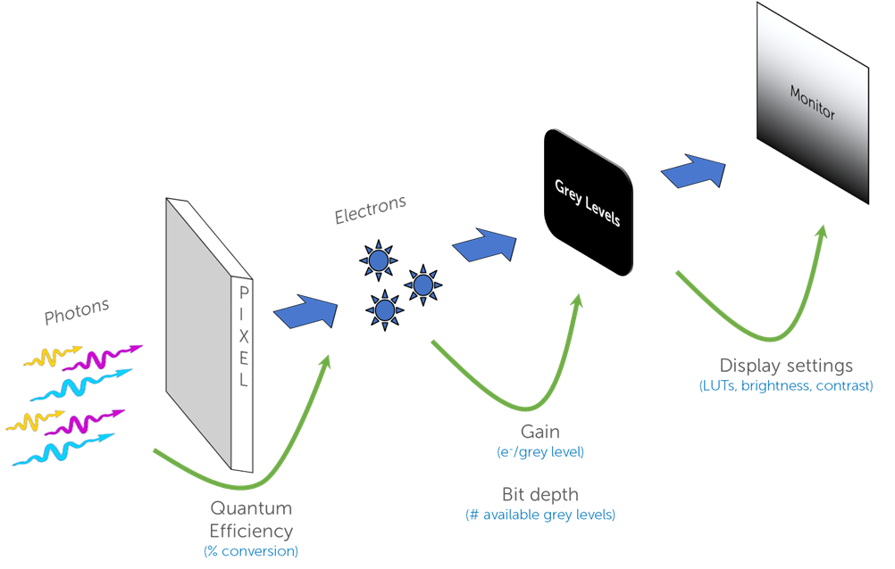
This process is the same for all camera technologies, but changes in each of these steps can optimize the end result. Some important camera factors to consider before discussing bit depth are full well capacity and dynamic range.
Full Well Capacity and Dynamic Range
As photons are converted to electrons by a sensor pixel, the electrons are stored in the silicon substrate of the pixel, known as a ‘well’. In different camera models or different modes in the same camera, these pixels have a different full well capacity, which is the maximum number of electrons they can store and still display as an image. Some cameras offer full wells up to 80,000 electrons, meaning extremely bright samples can still be displayed, whereas some are much lower (100-1000), meaning they are suited to lower signal levels. Full well should be considered if your sample level is very high (brightfield imaging), if your sample can get significantly brighter and change over time, or if you are attempting to image bright and dim objects in one image. However, most fluorescent applications have low signal levels and are suited to a lower full well capacity.
The dynamic range of a camera is related to the full well capacity, and it describes the ratio between the highest and lowest signals that can be displayed. This is calculated by simply dividing the full well capacity by the read noise, as these represent the maximum and minimum readable signals respectively. Dynamic range helps to analyze the change in your sample, how do you know your signal has doubled if the sensor cannot capture it?
This article describes another factor of scientific cameras that affects both the full well capacity and the dynamic range, namely the camera sensor bit depth, as well as how to best match your application and signal level to a suitable bit depth.
What Is Bit Depth?
Camera sensors convert photons into electrons, and these electrons are amplified into a voltage, which is the ‘analog’ signal. This signal goes through an analog-to-digital converter (ADC) and is converted into a ‘digital’ signal in order to be displayed as an image on a computer. The majority of scientific cameras are monochrome, meaning that the digital signal comes in the form of a grey level, ranging from pure black to pure white. The more intense the analog signal, the whiter the grey level, meaning that fluorescent images are typically displayed as a grey-white signal on a dark black background.
The signal is spread across the available range of grey levels, the greater the amount of signal, the more grey levels needed to fully display the image. If a signal had a peak of 5000 electrons, but the camera could only display 100 different grey levels, the signal would be compressed and every 50 electrons would be converted to one gray level, meaning that a signal would have to increase by over 50 electrons before a change could be seen in the image. This would make the camera insensitive to small changes in the sample.
In order to produce the correct number of grey levels to display the range of signal, cameras can operate at different bit depths. Computers store information as ‘bits’, where a bit can be 1 or 0. If a camera pixel was 1 bit, it would either be pure black or pure white and would not be useful for quantitative imaging. Each bit can display 2x grey levels, so 1 bit is 2 (21) grey levels and 2 bits is 4 (22) grey levels, as seen in Table 1.
As this is also a visual concept it is described visually in Fig.2, which shows the available grey levels at different bit depths from 1 bit to 14 bit.
| Bit Depth | Available Grey Levels | Available Grey Levels |
| 1 bit | 21 | 2 |
| 2 bit | 22 | 4 |
| 3 bit | 23 | 8 |
| 4 bit | 24 | 16 |
| 6 bit | 26 | 64 |
| 8 bit | 28 | 256 |
| 10 bit | 210 | 1024 |
| 12 bit | 212 | 4096 |
| 14 bit | 214 | 16,384 |
| 16 bit | 216 | 65,536 |

Scientific cameras typically use bit depths of 8 bit and above, as below this level there typically aren’t enough grey levels to display basic details in an image. This is shown by Fig.3, showing a typical cell image at different bit depths.
As seen in Figs.2 and 3, it is clear to see visual differences and improvements from 1 to 8 bit, but from 8-16 bits it is much harder to discern a visual difference, even though the number of grey levels doubles with each step. This is due to a number of limiting factors, including the computer monitor you are using to view this article, as well as the eyes you are using to look at the monitor. Computer monitors are limited to 8 bit per color channel, typically red, green, and blue (RGB). While these monitors can display over 16 million RGB colors (256 x 256 x 256), for monochrome viewing there are only 256 grey levels available, meaning your monochrome microscope images are being viewed as 8 bit through the monitor. This is similar to the human eye, which can see over 10 million colors, but only around 30-200 shades of grey. This poor grey vision is why we can struggle in low light conditions where colors are muted, and in areas of heavy snow.
Due to these limitations of eyes and monitors, monochrome images are typically viewed at 8 bit, even if the image was acquired at a higher bit depth. This is why quantitative scientific cameras are vital, as they can display how the signal is distributed among grey levels in an image and can detect differences in grey levels that are indistinguishable to the eyes.

Bit Depth and Scaling
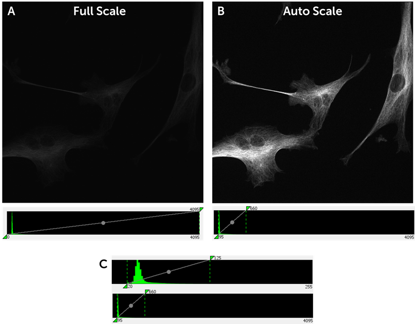
If you are using a 12 or 16 bit camera to capture signals of ~100 electrons, you will constantly be scaling your histogram to the very bottom, meaning the majority of available grey levels are wasted. An example of this can be seen in Fig.4, where a standard fluorescent cell sample is imaged at 12 bit. The signal can be distributed amongst 4096 grey levels, but only occupies a small part of this range (Fig.4A). Only by scaling the image down to this small portion of the full available range (~600 grey levels out of 4096) can the signal be optimally displayed (Fig.4B). A bit depth of 12 is unnecessary as most of the grey levels remain unused, this would be suited to a much higher signal level (500-1000 electrons).
The same signal is also shown at 8 bit, (Fig.4C) and with only 256 grey levels available the same signal is still easily accommodated. This represents how the signal would appear on the 8 bit mode of the Kinetix sCMOS, which still represents all the signal as data while running far more efficiently at higher speeds and with lower file sizes. For this signal level, you don’t need 12 or 16 bit.
Historical Bit Depths
Most scientific cameras operate at 8 bit or above, but different camera technologies have historically used different bit depths. The oldest camera technology, CCDs, used 8 bit in a different way. Classical 8 bit CCDs would scale to the camera full well instead of the signal, meaning that CCDs with around a 10,000 electron full well would be distributed amongst only 256 grey levels, giving you around 40-50 electrons per grey level. If a signal increased by 30 electrons, there would be no change in the grey level, meaning these 8 bit CCDs could not accurately represent the signal from the sample. This made it challenging to use these CCDs for fluorescence or low light imaging, and 12 bit CCDs became the standard from 2000-2010.
After CCDs came electron-multiplying CCDs (EMCCDs), which multiplied electron signals up to 1000x in order to increase the signal-to-noise ratio (SNR) for more sensitive imaging. Due to this multiplication signal levels were very high, meaning that EMCCDs were suited to a higher bit depth of 16 bit, spreading the signal over 65,000 grey levels. EMCCDs were well adopted by the scientific community due to the increased imaging speed and sensitivity compared to CCDs, and for a time the accepted bit depth for scientific imaging was 16 bit.
Due to the expense, EM decay, excess noise factor, low speeds, small field of view, and low resolutions, EMCCDs are being superseded by sCMOS sensors as a major imaging technology for the present day. As sCMOS sensors don’t use electron multiplication, received signals are not amplified and do not necessarily need the full range offered by 16 bit. As a result, sCMOS cameras can offer a more flexible range of bit depths.
Our Prime series of back-illuminated sCMOS cameras allow researchers to choose between 12 bit and 16 bit, with the majority using 12 bit due to the greater speed and most fluorescent imaging applications not needing a 16 bit range. Our newest camera, the Kinetix, goes one step further and offers 8, 12, and 16 bit modes. While early CCDs scaled 8 bit to the well, the Kinetix scales 8 bit to the signal, meaning that it can accurately detect and represent low light fluorescent signals at extremely high speeds and with half the file size. Our Prime and Kinetix cameras allow for flexible imaging with a bit depth that can be tailored to the signal level in the experiment. At this range of bit depths, data is being detected and presented, but it is vital for your imaging applications that your data is matched to depth. By changing from a 16 bit mode to 12 or 8 bit mode, there a many benefits.
Factors Affected By Bit Depth
With sCMOS cameras offering a range of bit depths for different applications, it is good to know what happens when bit depth is changed and the benefits to imaging.
Imaging Speed
At lower bit depths there are less possible grey levels to convert the signal to, this makes the conversion process much faster. With our sCMOS cameras, the 12 bit modes run at double the readout speed compared to 16 bit modes, which makes 12 bit essential when high speeds are required. For example, the Prime 95B can only access the full 80 fps at full frame (1.4 megapixels) when in 12 bit mode.
A further drop to 8 bit allows for extremely high speeds, for certain applications such as calcium/voltage imaging or when working with live, dynamic samples when speeds of >1000 frames per second are needed. The Kinetix operates at 500 fps at full frame (10 megapixels) when in 8 bit mode, allowing researchers to capture more than ever before. For high-speed applications, 16 bit mode is a limiter on the acquisition speed, especially as signal levels are likely to be low due to the low exposure times needed to achieve high-speed imaging.
File Size
In computer storage terms, 8 bits make up 1 byte, with storage in terms of megabytes, gigabytes, terabytes, etc. This means that 8 bit images take up one byte of data, and bit depths above 8 require more than one byte, with 12 and 16 bit images being scaled up to two bytes. This means that images taken with 12 or 16 bit have double the file size compared to 8 bit images. The Kinetix can not only acquire images at extremely high speeds in 8 bit mode, but data storage and transfer become far easier.
When taking high-speed or time-lapse acquisitions across multiple wavelengths or XY positions, experiments can accumulate vast numbers of images. Transferring or analyzing these large datasets takes up a large amount of computational processing power and time, at considerable inconvenience to the researcher. By dropping to 8 bit, images will be half the file size and become far more manageable. This results in easier data transfer, an issue which is becoming more and more important as camera speeds and sensor sizes continue to increase.
Dynamic Range
The dynamic range of a scientific camera is essentially the sensor’s ability to read very bright and very dark signals together. If a camera has a dynamic range of 4000 : 1 (ratio of highest to lowest detectable signals), it can only detect 4000 levels of signal, and using a 16 bit mode with 65,536 grey levels would be inefficient, this dynamic range is better suited to a 12 bit mode (4096 grey levels). Higher bit depth does not translate directly into a higher dynamic range, higher bit depths simply slice the signal more finely and do not affect the ratio between the highest and lowest brightnesses that a sensor can detect.
Gain
While bit depth dictates the number of available grey levels for the signal to be distributed amongst, the gain is the factor that determines how many electrons per grey level. If the gain is 1x, an increase in signal of 1 electron results in an increase in the grey levels. With sCMOS cameras, different bit depths often have access to different gain states. This is important for imaging as certain gain states have different read noise, making a selection of bit depth and gain state vital for low signal levels.
Signal Level Considerations
sCMOS cameras offer a range of different bit depths, but it is important to know which is best for your application. Every imaging experiment is unique, working with different samples, light levels, and speeds. All of these factors affect which bit depth is right for your application. The main piece of information to know is the signal level, here are some factors to consider:
- Brightfield or Fluorescence? Fluorescent signals are several magnitudes below brightfield signals (see Fig.4), meaning that most fluorescent imaging experiments have a lower signal level.
- Is your sample live or fixed? High-intensity light sources can induce phototoxicity and adverse effects on live samples, and there is a far smaller range of fluorescent probes/markers available for live samples when compared to fixed cells/tissues. Live samples typically produce lower signal levels.
- Are you imaging at high speed? In order to achieve a high acquisition framerate, low exposure times are needed. Only by exposing for 1 ms or less can speeds of 1000 fps (1kHz) be reached, this means the camera has very little time to collect the signal. High-speed imaging typically results in lower signal levels.
- Confocal or widefield? By their nature laser-scanning and spinning disk confocal systems use pinholes to block out-of-focus light and illuminate small sections of the sample, this light-rejection technique typically results in lower signal levels compared to widefield techniques, where the entire sample is illuminated.
- Visible light, UV, or infrared? Scientific cameras are typically most sensitive at wavelengths in the visible light spectrum. If your imaging involves ultraviolet, near-infrared, or infrared imaging, acquired signals will lower due to decreased camera quantum efficiency at these wavelengths.
Imaging fixed cells with a high-intensity laser and a widefield system would result in a far higher level of signal when compared to a high-speed spinning disk confocal system that images live cells or model organisms. By knowing your typical level of signal in your experiments, you can match this up to an optimal bit depth.
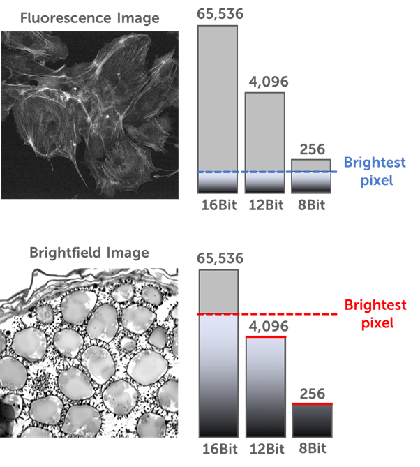
Despite the differences in signal between fluorescence applications, this signal is still magnitudes below brightfield imaging. While fluorescent applications (live or fixed) rely on the detection of light emitted from the sample (in response to excitation light), this emitted signal is typically many times weaker than the excitation signal. In addition, the signal is limited to marked areas on the sample, meaning the majority of the image is black and the sample is white. With brightfield, samples are directly illuminated by light from a bright lamp being transmitted through the sample, with areas absorbing light. This results in an image where the sample is dark but the background is white, and the direct illumination means that signal is many times higher.
For brightfield applications, higher bit depths (16 bit) are a must due to the signal intensity. However, the same is not true of fluorescent applications, which often feature far lower signal levels and are typically not suited to higher bit depths such as 16 bit. For the majority of fluorescence imaging, 12 or 8 bit is optimal, which has the added benefit of increasing the image speed and decreasing the file size. A comparison of the signal intensities between fluorescence and brightfield can be seen in Fig.5.
With fluorescent applications, the data should be matched to bit depth. The lower signal levels are better suited to 8 or 12 bit, by imaging low signals at 16 bit you are limiting imaging speed and unnecessarily increasing file size. Have a look at your application and signal level, and determine which bit depth is best for your imaging.
Summary
Bit depth is an important factor involved when imaging with scientific cameras. By changing how the signal is presented, imaging can be done more efficiently: lower bit depths allow for greater imaging speed, smaller file sizes, and more efficient data transfer, with no downsides. With fluorescent imaging delivering typically low signal levels, see how your imaging systems could adapt to lower bit depths.