
Introduction
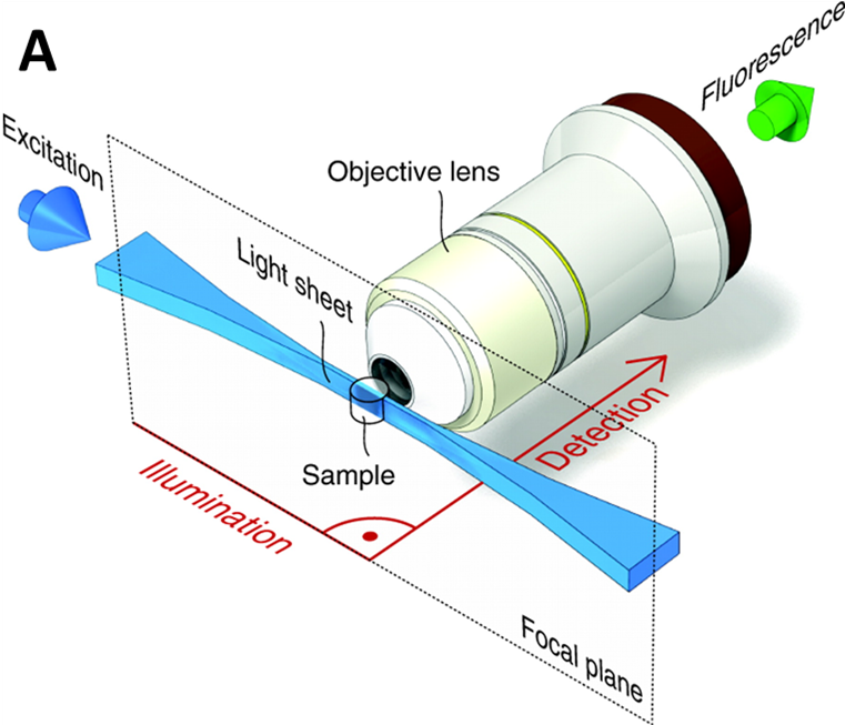
Light sheet microscopy, otherwise known as selective plane illumination microscopy (SPIM), is a well-established 3D imaging technology for its ability to image large samples quickly and with high resolution in 3D. In contrast to conventional 3D imaging technologies, the sample illumination path is perpendicular to the fluorescence detection path in light sheet microscopy, as seen in Fig.1. This, combined with the thin ‘sheet’ of light used to illuminate the sample (rather than a wide beam), excites a thin section of the sample near the detection focal plane, which not only offers excellent optical sectioning ability, but also reduces the photobleaching and photodamage, and increases the axial resolution. These advantages are further increased the thinner the excitation light sheet can get.
However, when a light sheet is applied to large specimens it is necessary for the imaging system to have a large field of view (FOV), which means the light sheet has to be closely confined to the detection focal plane over increasingly long distances. This can make light-sheet imaging at large FOVs very challenging, as the light sheet diffracts and spreads out over longer distances, affecting the normally high resolution of the technique.
This problem was addressed by Liang Gao and colleagues, who stated in a 2016 paper: “A key problem using SPIM turns out to be how to increase the FOV without losing the spatial resolution and optical sectioning capability. Different approaches other than finding a perfect light-sheet must be made.” Gao and team later developed a new technology which they called tiling light-sheet SPIM (TLS‑SPIM).
Tiling Light Sheet
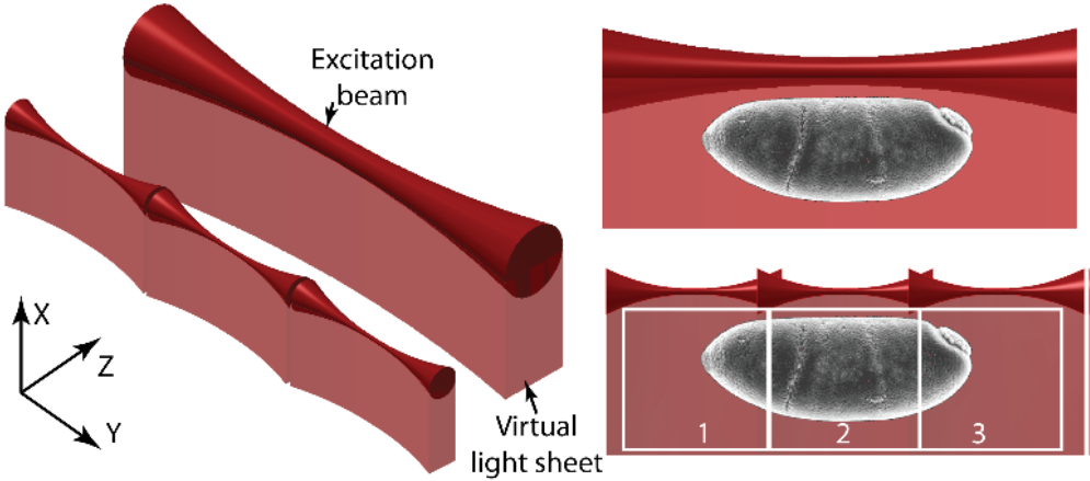
In TLS-SPIM, multiple small light sheets are ‘tiled’ together. These small light sheets are very thin, improving optical sectioning and image resolution, but reducing the FOV. But as multiple light sheets are tiled together, they each image a part of the sample and the whole FOV can be reconstructed by combining the images together. The difference between SPIM and TLS-SPIM can be seen in Fig.2.
As an image is collected at each tiling position, and these images are then combined together (to show the whole FOV) in post-processing steps, the imaging speed is reduced compared to standard SPIM. This loss of speed is countered by the higher resolution and better optical sectioning across large FOVs with large samples. This allows TLS-SPIM to increase the FOV of light sheet microscopes without compromising.
In order to implement TLS-SPIM, either the specimen or the excitation light sheet has to be quickly shifted along the Y-axis during imaging. A phase-only spatial light modulator (SLM) is used to defocus the light sheet and move it quickly within the image plane, as this is far more efficient than moving the sample or microscope objectives to achieve the same thing.
Advantages
There are several advantages to the light sheet design used in TLS-SPIM, including but not limited to:
- No compromise is made between axial resolution, optical sectioning and FOV
- Tiling can be done with any kind of SPIM or light sheet technique
- The signal to noise ratio (SNR) is improved, as there is less background fluorescence
- The thickness and the number of tiled light sheets can be adjusted flexibly according to the specimen to be imaged and the specific imaging requirements, making TLS-SPIM very flexible
- In addition, because the excitation numerical aperture (NA) is usually low, a light sheet can tile for several millimeters with very little influence on its intensity profile
- Some applications only desire to image small areas within a large FOV, making TLS-SPIM a very efficient option (as opposed to imaging the whole FOV)
- Multicellular specimens are more suited to TLS-SPIM
Examples
As several papers have been published featuring TLS-SPIM microscopy, there are a number of images highlighting the large FOV and high resolution of the technique, as seen in Fig.3. These images are from a range of different sample sizes, from single cells to entire organs (Fig.3F/G show TLS-SPIM on cleared mouse organs), showing the increased FOV, as well as the high resolution available on smaller samples. TLS-SPIM can also allow researchers to choose whether to prioritize speed or resolution, with high speed in Fig.3D and high resolution in Fig.3E.

Recent studies using FRET involve the visualization of protein conformational changes, specifically enzymes during their functional cycle (Dyla et al. 2016) and monitoring DNA synthesis in real-time (Fijen et al. 2017). For more details on the legacy of FRET and it’s developments into the future, see the review by Sun et al. 2011.
Cameras
As TLS-SPIM comes at the cost of speed compared to SPIM, it is important to use cameras that can offset this loss of speed. The latest sCMOS cameras can image 100s of frames per second (fps) across an entire sensor, and up to 1000s of fps if TLS-SPIM is defining several smaller regions of interest (ROIs) within a larger sample.
In general, a high speed, high resolution, and high quantum efficiency (QE) camera is required to take the full benefit of the TLS-SPIM. The inclusion of small pixels and a large FOV significantly reduces the time of imaging the whole sample, whilst giving an improved resolution at low magnification.
Because of its small photobleaching and phototoxic effect, light sheet microscopy is also a good choice for low light and live-cell imaging. A camera that can acquire images at video rates, full-frame, allows imaging dynamic events moving at high speed over long time scales. Other advantages such as a high peak QE and low read noise gives high sensitivity for dim signal detection and allows for short exposure times to further minimize the photodamaging effect of light.
Summary
Conventional SPIM light sheet often has to compromise between axial resolution, optical sectioning capabilities, and FOV, as even the perfect light sheet is subject to diffraction, and loses resolving ability over large distances and wide FOVs.
Tiling light sheet (TLS-SPIM) presents a solution to this compromise by replacing the standard light sheet with several smaller (and therefore thinner) light sheets that are ‘tiled’ together, allowing for individual high resolution images to be stitched together into a large FOV. This allows TLS-SPIM to not compromise, producing high resolution images with a large FOV, presenting a powerful imaging platform to researchers.
References
Gao L. (2015) Extend the field of view of selective plan illumination microscopy by tiling the excitation light sheet. Optics express; Mar 9; Vol. 23, No. 5; doi:10.1364/OE.23.006102
Fu Q., Martin B.L., Matus D.Q. and Gao L. (2016) Imaging multicellular specimens with real-time optimized tiling light-sheet selective plane illumination microscopy. Nat Commun 7, 11088 doi: /10.1038/ncomms11088
Wang D., Jin Y., Feng R., Chen Y., Gao L.,(2019) Tiling light sheet selective plane illumination microscopy using discontinuous light sheets. Optics Express, Vol 23, no 23, Nov 2019, 34472.
B.-C. Chen, W. R. Legant, K. Wang, L. Shao, D.E. Milkie, M.W. Davidson, C. Janetopoulos, X.S. Wu, J.A. Hammer, Z. Liu, B.P. English, Y. Mimori-Kiyosue, D.P. Romero, A.T. Ritter, J. Lippincott-Schwartz, L. Fritz-Laylin, R.D. Mullins, D.M. Mitchell, J.N. Bembenek, A.C. Reymann, R. Böhme, S.W. Grill, J.T. Wang, G. Seydoux, U.S. Tulu, D.P. Kiehart, E. Betzig (2014) Lattice light-sheet microscopy: Imaging molecules to embryos at high spatiotemporal resolution, Science 346, 1257998.
Gao, L.,* Shao, L., Chen, B.C., Betzig, E. (2014) “3D Live Fluorescence Imaging of Cellular Dynamics Using Bessel Beam Plane Illumination Microscopy”, Nature Protocols, 9, 1083-1011. (*Corresponding Author, Cover article)
Gao, L., Shao, L., Higgins, D.C., Poulton, J.S., Peifer, M., Davidson, M.D., Wu, X., Goldstein, B., and Betzig, E. (2012), Non-invasive imaging of 3D dynamics in thickly fluorescent specimens beyond the diffraction limit, Cell, 6, 1370-1385.
Planchon, T.A.,* Gao, L.,* Milkie, D.E., Davidson, M.W., Galbraith, J.A., Galbraith, C.G., Betzig, E. (2011) Rapid three-dimensional isotropic imaging of living cells using Bessel beam plane illumination, Nature Methods, 8, 417-423. (*Equal Contribution, Cover article)
Li X, Zhang D, Wang C, Li X, Lai M, Weng Y, Feng R, Zhang XS, Chen Y, Yu L, Wang D, Nie R, Yang X, Chen Y, Chen BC, Feng Y, Zhou B, Cai S, Jia JM, Gao L. (2019) A versatile tiling light sheet microscope for cleared tissue imaging, bioRxiv 829267; doi: https://doi.org/10.1101/829267
Our thanks to Liang Gao (School of Life Sciences, Westlake University) for comments on the text.