
Introduction
At its core, a typical microscope is essentially a box designed to hold two lenses in precise positions so that light can be accurately magnified from the sample to the detector. The first of these two lenses is the objective lens, which is located close to the sample, moves when the focus dial is turned and has useful information such as magnification written on its side. The second is commonly referred to as the tube/collector lens, which is buried deep within the body of the microscope and rarely seen.
As well as these lenses, microscopes consist of:
- Light sources such as a lamp or laser
- Detector, typically a scientific camera
- Eyepiece, a binocular-like device for the human user to directly observe the sample
- Stage for the sample to sit on/be mounted to
- Mechanical controls such as diaphragms, filters, dials in order to manipulate the light path or the position of the lenses
- Digital controls such as the microscope software, where factors like exposure or field of view can be controlled
- Additional lenses/mirrors in order to further manipulate the light path
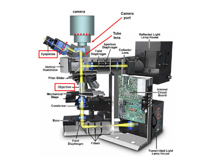
These components are responsible for the magnification, resolution, and field of view inherent in the microscope. In this article, the details of microscope components and anatomy are explained in relation to how they contribute to providing the best possible image. In order to see the arrangement of these components, see Fig.1.
Lenses
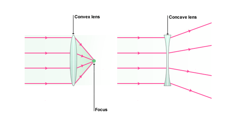
A lens is an optical device that can refract light. The refraction depends on the shape of a lens, which is typically convex or concave. For the purposes of microscopy, convex lenses are used for their ability to focus light at a single point. This is how the human eye works, with the convex biological lens focusing light on the back of your eye where rod and cone cells can detect it. Microscopes borrowed this idea, using convex lenses to focus light towards a point that is f distance away from the lens. This distance is known as the focal length of the lens and depends on the shape. Lens shapes can be seen in Fig.2. It should be noted that these lenses are symmetrical and will have the same effect on light from either direction.
The focal length of a microscope objective lens needs to be very small, as the objective is often very close to the sample. Typically, the higher the magnification, the closer the objective needs to be.
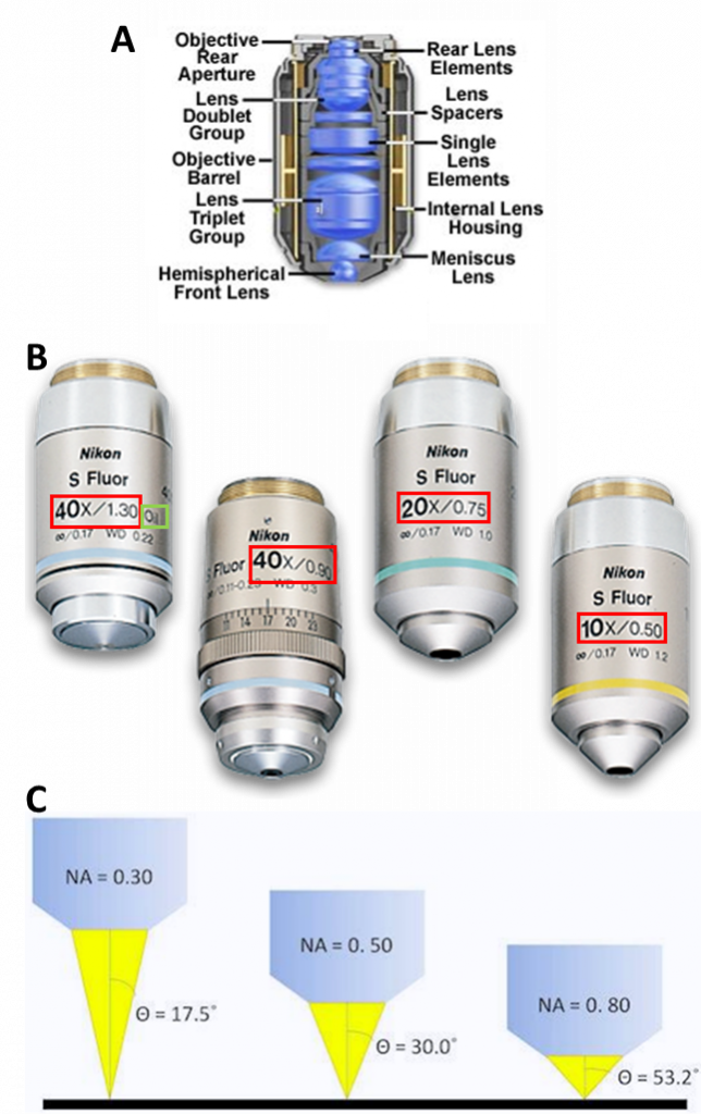
Microscope objectives contain lenses but are not as simple as the lenses seen in Fig.2, making them complex lenses (Fig.3A). While the overall effect can be magnification, these lenses are carefully designed to control a variety of aspects of lenses, such as working distance, and the ability to correct problems such as aberrations. Objectives are characterized by two factors: magnification and numerical aperture (NA). Objective magnification ranges from 2x to 100x (and is combined with the eyepiece magnification), magnifying the sample 2-fold to 100-fold respectively (Fig.3B). NA is related to the focal length of the lens, namely what angle light exits/enters the objective, as this affects the resolution (Fig.3C, read our app note on resolution and NA for more). See Fig.3 for more information.
Field and Aperture Stops
There are always constraints to the area to be imaged and the detailed information a microscope provides. There are physical blocks in the light path, typically named stops, diaphragms, or apertures. Here, the term stop will be used. For the imaging path, they may or may not be adjustable by the user, but as discussed later, the same concepts apply to the illumination optics.
The aperture stop is the part of the imaging system that limits the range of angles of light the lens can collect from the sample. This range of angles defines the lens NA and therefore the system resolution, the ability to detect two objects as different. Most microscope objectives are designed such that the aperture stop is the Objective Rear Aperture, as seen in Fig.3A. This ensures that the objective defines the system resolution and that the resolution is the same across the entire field of view.
The field stop limits the area that can be imaged. This can’t be bigger than the diameter of the tube lens. At best, the area imaged is the diameter of this lens divided by the magnification. If the internal lens has a diameter of 25 mm and the magnification is 100x, one should see a circle with a diameter of 250 µm of the sample. Things such as light modifying elements, or the detector itself, can easily reduce the field of view that is collected.
Detectors
Eyepieces
The output of most microscopes is an image about 2 cm across, so this is typically magnified again in order to fill the field of view of the eyes. Eyepieces, another magnification system, give between 10x to 30x magnification on top of that provided by the objective and microscope. In combination with the lens in the eye, this magnifies the image to the retina at a useful scale, so that the human eye may resolve and observe objects even as small as cells (~10 µm).
Scientific Cameras
There are all kinds of cameras that can be used with a microscope. Key experimental considerations are the sensitivity, resolution, field of view and speed of a camera. For a detailed explanation, see our articles on these subjects.
A camera pixel is the individual light-measuring unit in the camera, and the camera’s sensor has arrays of pixels to measure the light across the field of view. A camera might have as few as 128×128 pixels, or as many 5000×3000 (15 million pixels, or 15 megapixels) or more. Since microscope camera ports commonly have the same approximate size, cameras with larger pixel arrays usually have smaller individual pixels.
Pixel size is key to being able to image with the full information content provided by the optics. Camera pixels are square and usually 3-24 µm along the edge. Generally speaking, cameras with smaller pixels allow for higher resolution imaging whereas cameras with larger pixels have a larger surface area for photon collection making them more sensitive.
Most microscopes have optical exit ports with a diameter of around 18-25 mm. Using no magnification (1x objective), the image would, therefore, cover 18-25 mm of the sample. Given the fixed size of the image, camera sensors with diagonal dimensions greater than the microscope camera port would have pixels with no light falling on them. Therefore, it is important to match the field of view of the camera with the maximum field of view of the microscope.
Bigger pixels have benefits to sensitivity. Indirectly, they also have benefits on the total time it takes to get the information out to the computer. Total readout time is dependent on camera architecture, with CMOS being faster than CCD, but also on the total number of pixels in the camera. In general, a camera with bigger but fewer pixels will be ready for the next exposure faster that a camera with more, smaller pixels.
Illumination
Various microscopy methods detect specific interactions between light and the sample. Methods that image scattered or absorbed light focus illumination light to the sample using a separate illumination lens and imaging objective. The focusing illumination lens is referred to as a condenser, with its own properties of working distance, NA, etc.
Fluorescence microscopy uses reflection or epi-fluorescence geometry, where the objective serves as both the illumination condenser and the imaging lens. The illumination light is passed through the objective and the detected light is passed backward through the objective and split off to a camera or eyepiece. One benefit of this approach is that light that doesn’t interact with the sample travels away from the detector, maximizing separation of illumination light from fluorescent emission. The transmission and epi-fluorescence light paths are illustrated in Figure 4.
Two illumination methods, critical or Köhler, are commonly used to illuminate the sample in microscopy. The primary difference is whether they copy the structure (critical) or scramble the structure (Köhler) of the illumination source at the sample. As Köhler illumination is more frequently used, it will be covered in this article.
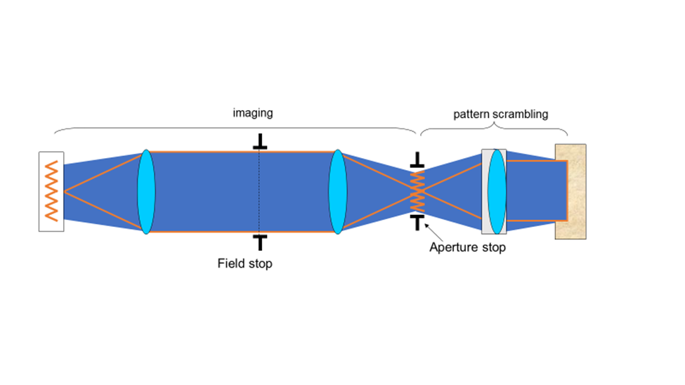
Köhler invented a focusable illumination system that allowed control of the field size, the power and the angle of illumination while scrambling the structure of the light source projected on the sample. He took advantage of the property of a lens to convert the lateral structure into parallel rays to do this. Putting an illumination source at the focal point of the lens transforms the output into uniform light rays on the other side, scrambling any structure inherent in the source. Multiple points emitting from the light source all end up scrambled and traveling in parallel rays after exiting the lens
Putting the illumination source close to the sample limits control of light intensity and illumination field of view. Köhler imaged the light source to a focal length from the condenser lens, as illustrated in Fig.5. This provides control of the field of illumination, with a field stop in the middle of the imaging component and an aperture stop 1f away from the condenser. The aperture stop is a highly significant aspect of the design; allowing easy control of the light power to the sample. These stops usually have levers allowing the user to manually adjust the illumination area (field stop) and power (aperture stop) being delivered to the sample.
Light Sources
There are a variety of lamps, light-emitting diodes (LEDs) and lasers that can be used to illuminate the sample in the microscope. Typical lamps used for illumination include:
- Halogen lamp. These provide broad-spectrum illumination and their power output is related to the voltage across the filament. Often used for transmission imaging.
- Xenon arc lamp. Has uniform power across commonly used wavelengths. In the bulb, electricity arcs across two metal points in a high-pressure xenon atmosphere creating a plasma near the metal points. Sometimes used for fluorescence imaging.
- Mercury/metal halide arc lamp. Has an overall greater power at commonly used wavelengths than xenon lamps. Also generates a plasma using electrical discharge between two metal posts. Though the power at various wavelengths can change dramatically, mercury lamps are often used for fluorescence imaging. Needs to cool down between uses.
The useful life of each of these sources varies between a few hundred hours for mercury arc lamps, to 1000-2000 hours for mercury/metal halide and halogen lamps.
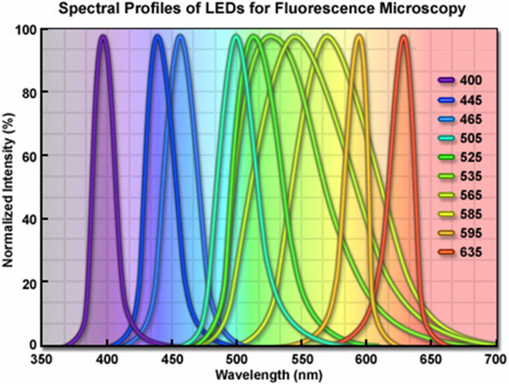
LED light sources are powerful enough to compete with xenon and mercury/metal halide lamps as illumination sources for fluorescence imaging. Each LED has a unique color, so LED broad band sources are derived from arrays of multiple individual diodes of relatively narrow spectra. LED sources have lifetimes of 10,000+ hours of use and are highly energy-efficient, making them very economical over long term use. They can be turned on and off quickly, over nanoseconds, making them useful for experiments requiring tight control of illumination. The spectral distribution of an example LED light source is illustrated in Fig.6.
Lasers provide light with highly specific wavelengths. For example, the light generated by a helium-neon (HeNe) laser has a color of 632.8 nm. Unlike the other light sources discussed here, lasers provide coherent light. Coherence indicates that the light is highly structured, with all the peaks and troughs of the light wave occurring at the same time and place. Coherence is necessary when focusing light to a diffraction-limited point, but also complicates widefield illumination due to its tendency for positive and negative interference. This self-interference can often be detected as a speckle pattern in an expanded laser beam.
Filters
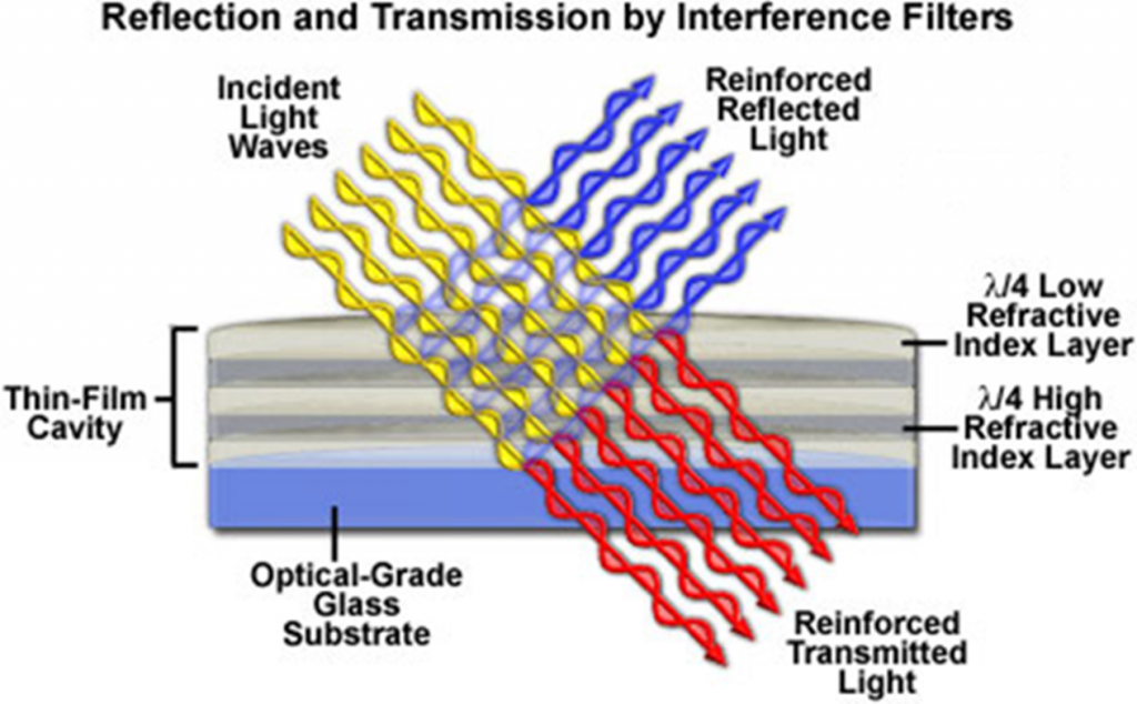
Filters are optical components that can transmit certain wavelengths of light while reflecting others. Color selection is critical for fluorescence imaging. An example of optical filtering is shown in Fig.7.
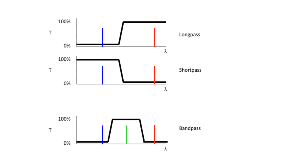
Filters are commonly referred by the nature of their transmission, and the wavelength where they switch from transmission to reflection, as illustrated in Fig.8. A 500 nm short pass (SP) filter would transmit light bluer than 500 nm and reflect light redder than 500 nm. In contrast, a 500 nm long-pass (LP) filter will transmit light longer than 500 nm, reflecting light of shorter wavelengths.
By combining the properties of SP and LP filters, bandpass (BP) filters were created. A SP 550 nm filter combined with a LP 500 nm filter would transmit light only between 500-550 nm. BP filters are usually described by their center wavelength and the allowed wavelengths to either side. A hypothetical SP550, LP500 filter combination is commonly referred to as BP 525d25, a BP centered at 525 nm with 25 nm transmission permitted to either side (Reichman, 2017).
In the fluorescence microscope, a combination of excitation BP filter, a LP dichroic filter and an emission BP filter are organized into a cube holder to provide high-intensity excitation light to the sample and efficiently isolate emission light before steering it off to the camera.
Summary
The parts of the microscope discussed here work in concert to send light to the sample and take the light from the sample and magnify it up to the detector for collection. Aperture stops, usually in the objective, limit the microscope resolution. Field stops limit the area illuminated or detected. Components such as objectives, light sources, filters, and cameras all must be considered to get the best possible image.
References
Abramowitz, M. 2003 Microscope Basics and Beyond, Olympus America, Scientific Division.
Davidson, M.W. Koehler Illumination in the Zeiss Basic Resources website (https://www.zeiss.com/microscopy/us/solutions/reference/basic-microscopy/koehler-illumination.html)
Parry-Hill, M.J., Vogt, K.M, Griffin J.D., and Davidson, M.W. Matching Camera to Microscope Resolution in the MicroscopyU website (https://www.microscopyu.com/tutorials/matching-camera-to-microscope-resolution)
Reichman, J. 2017 Handbook of Optical Filters for Fluorescence Microscopy. Chroma Technology Company Bellows Falls, Vermont 05101-3119 (https://www.chroma.com/sites/default/files/HandbookofOpticalFilters.pdf)
Spring, K.R., Parry-Hill, M. & Davidson, M.W. Geometrical Construction of Ray Diagrams in the Olympus Microscopy Primer website (https://www.olympus-lifescience.com/en/microscope-resource/primer/java/components/characteristicrays/)
Spring, K.R., Parry-Hill, M., Burdett, C.A., Sutton, R. T., Fellers, T.J. and Davidson, M.W. Laser Fundamentals in the Olympus Microscopy Primer website (https://www.olympus-lifescience.com/en/microscope-resource/primer/lightandcolor/laserhome/)