
Introduction
A microscope camera mount (also known as a lens mount) is an essential piece of hardware that interfaces between a scientific imaging camera and photo port of a microscope. This is an essential interface that secures the camera to the microscope. Without the correct camera mount, a camera cannot be used correctly with a microscope system.
There are several factors to consider when selecting a camera mount, particularly, the type of microscope the camera needs to mount to, the make and model of the camera being attached and whether additional optics within the camera mount are required or desired. This will help determine which type of mount is necessary.
Mount Basics
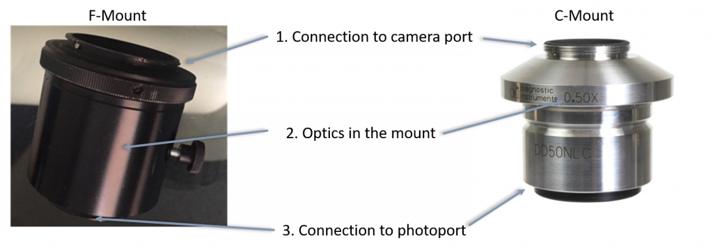
A camera mount comprises of three main parts:
- The connection to the camera (C-mount, F-mount, T-mount)
- Optics in the mount (additional relay lens)
- The connection to the photo port (microscope specific)
Firstly, it is necessary to know what type of camera the mount needs to attach to as this will generally determine what type of thread the mount should have, whether it will be a C- or an F-mount for example. As camera mounts are standardized, any C-mount camera can use any C-mount adaptor (on the camera connection side).
Secondly, it is important to match the camera mount to the microscope system. The microscope connection end of the mount will be specific for the photo port of the microscope brand it is designed for. Therefore, different microscopes will require different mounts to ensure successful attachments and mounts cannot usually be switched between different microscope brands.
Finally, all microscopes will have different diameter photo ports and the formation of the image will occur at different distances away from the ports, so additional relay optics might be desired if the components are not carefully picked to optimize factors such as magnification, resolution, and FOV. However, where possible, additional optics should be minimized in systems as additional lenses contribute to loss of light and reduction in image quality.
Different microscopes will also have differences in their configuration and optics and will, therefore, have different focal points. Ensuring the correct mount is selected will also ensure that optimal image quality is obtained. If an incorrect mount is used for the microscope, things such as parfocality (ability to focus at both the eyepiece and camera) and focus will not be maintained, thus the image quality will suffer.
Using Additional Optics In Camera Mount Adapters
Additional optics are often referred to as tube lenses or relay lenses and these are typically used to trade-off the FOV of the microscope, effective pixel size, and the resolution.
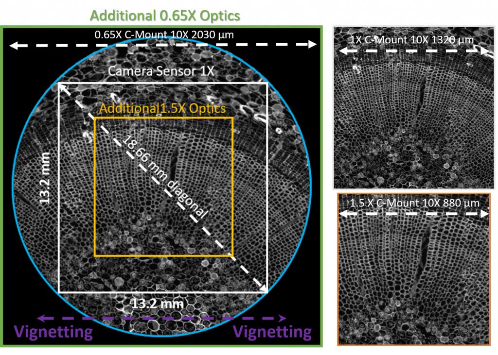
Due to the nature of the microscope photo port (which is typically circular) and the available camera sensor field of view (typically rectangular or square), the camera FOV will never exactly match the full area possible on the microscope. Therefore, it is common practice to match the circular diameter of the microscope photo port with the rectangular diameter of the camera sensor, such as an 18.66 mm diagonal sensor used with a 19mm diameter photo port (Figure 1). A larger sensor camera could be used but then there would be vignetting at the corners of the image which is to be avoided.
It is optimum to match the FOV of the microscope to the FOV of the camera, however, it is also possible to image with camera sensors that are smaller than the maximum FOV of the microscope. In this case, the image FOV will be smaller than the maximum available microscope FOV but this can be compensated for by using mounts with additional optics to demagnify the image.
Demagnification using C-mount optics allows the user to trade off sampling at a higher resolution for an increase in FOV, likewise, magnification using C-mount optics would do the opposite. A demagnification (<1x) coupler increases FOV but in doing-so increases the effective pixel size in sample space. Conversely, when a magnification coupler is used (>1), this leads to a decrease in effective pixel size at the expense of a smaller field of view.
Available C-mount couplers generally range from 0.5x (halved) up to 2x (doubled). Camera sensor sizes can vary by a large amount (from 6 mm to 32 mm). Thus, the C-mount coupler desired will vary depending on the size of the camera sensor. The smaller the camera sensor, the more demagnification necessary to maximize the FOV. Generally, the size of the CCD as a decimal will indicate roughly what is required in the coupler magnification, for example, a 11 mm CCD requires a 0.7x mount to maximize the FOV (Table 1).
| Camera Sensor Size (mm) | Diagonal (mm) | Adaptor for max FOV | Microscope FOV (mm) |
| 8.46 x 8.46 | 6 | 0.3x | 16 |
| 12.7 x 12.7 | 8 | 0.45x, 0.5x, 0.6x | 16 |
| 16.9 x 16.9 | 11 | 0.7x | 16 |
| 25.4 x 25.4 | 16 | 1x | 16 |
Table 1: Guide to matching the sensor FOV to the microscope FOV using different additional optical adaptors in the camera mounts to maximize imaging area on a microscope with a FOV of 16 mm^2.
If a mount is used that leads to ‘over de-magnification’, then the sensor size will be greater than the microscope FOV and this will lead to an artifact called vignetting (Figure 1). This leads to the visualization of the edge of the circular microscope FOV. This problem can be overcome by demagnifying less.
Disadvantages of using additional C-mount optics to modify the pixel size include the unavoidable loss of light (3-4%) due to additional lenses in the light path, as well as the potential for reduced image quality due to poorer lens quality and uneven illumination of the sensor. Therefore, it is more widely recommended to use larger format sensors, with pixel sizes appropriate for the magnification in the system, to maximize both FOV and resolution and negate the need for use of a magnifier or demagnifier in the mount.
Types Of Camera Mount
There are a wide variety of different camera mount types. The most well-known scientific camera mount types are the C-, T- and F- mount. They are generally defined by their thread specifications, but most mount types also have a standard flange focal distance. Flange focal distance defines proper distance for the image to be focused on the sensor and is the distance between the flange of the lens and the focal plane of the lens (where the camera must be positioned).
A 1x adaptor does not have any incorporated optics, making them cheaper than other types of mounts. In this situation the maximum camera field of view will depend only on the size of the camera sensor and the diameter of the photoport. These mounts only act as an adaptor to secure the camera to the imaging system.
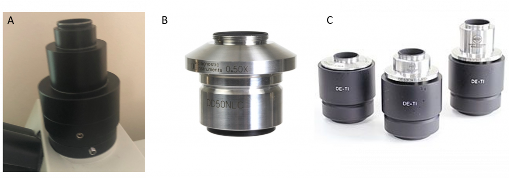
Mounts can also be used to introduce additional optics into the light path, and there are a variety of different mounts available which can be identified by the number written on the side. These generally range from 0.35x up to 2x and trade off resolution with field of view (FOV).
C-Mount
A traditional C-mount adaptor is very common for connecting cameras and microscopes. These mounts have typically been used as the industry standard and are generally the lowest cost and the most effective as the microscopy manufacturing industry has standardized to this type of mount – anything different is less common.
All C-mount adaptors provide a male thread that fits the female thread on a camera. This permits the connection of any C-mount microscope camera directly to the adaptor. All C-mount adaptors have a universal 25.5 mm diameter thread with 32 threads per inch and a flange focal distance of 17.52 mm. Because of the relatively small diameter of the C-mount connector, it is not suitable for larger sensors (>22 mm).
A C-mount without a lens within is known as a 1x C-mount and the only function is as an adaptor for the camera to the microscope to secure the camera to the system. C-mount adaptors are microscope specific. Therefore, the lens within the C-mount is specific to the microscope that is purchased, for that reason, it is essential to pick a C-mount that is specifically designed for the microscope it is to be fitted to.
Some C-mounts will permit focusing which allows the eyepiece and the image to be in focus at the same time, which is a useful function called parfocality.
Although C-mounts are the most widely used mount in microscopy imaging. They are restricted to a maximum FOV of up to 22 mm FOV. Therefore, if FOVs greater than this are required the C-mount will no longer be the mount of choice.
F-Mount
Recent technological advancements have led to the introduction of larger FOV microscope imaging systems which led to the need for larger format camera adaptors to permit the use of these FOVs.
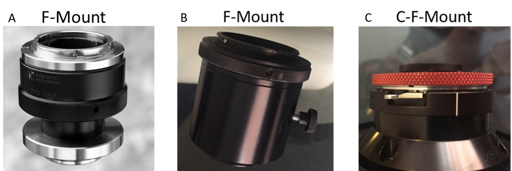
The F-mount is a unique mount in that, rather than being a thread mount, consists of a bayonet-style mount with a turn and lock tightening mechanism. The F-mount was originally developed for Nikon SLR cameras, but, due to their large diameter, the F-mount is also ideally suited for the newly developed large FOV microscopes (>22 mm). F-mount adaptors permit a FOV of greater than 30 mm, and they also have a long back focal distance which allows them to be converted to C mount adaptors with the addition of an F to C adaptor ring.
Cameras, therefore, only use the F-mount under two conditions:
- When the imaging sensor exceeds the 22 mm C-mount size limit
- When a larger back focal distance is required (additional space) for other optical elements
T-mount
The T-mount is an unusual mount as, unlike others which are not interchangeable between manufacturers, the T-mount allows for inter-manufacturer compatibility. The T-mount offers the possibility of a single standardized mount, not only for microscopes but also for other optical equipment such as telescopes and slide duplicators.
The T-mount system consists of the camera, a T-adaptor, a T-ring and a lens or telescope. Cameras generally do not have T-mounts, therefore T adaptors or T2 adaptors must be used. On the rear side of the adaptor, the mount would be appropriate to the brand and model camera that would attach to it and on the front of the adaptor is a female threaded connector matching the T thread of the lens.
Summary
Like all aspects of designing optical systems and components, the correct identification of camera mount necessary for the imaging system is critical to obtaining the best images possible devoid of artefacts with maximum resolution, magnification and FOV.
Most microscope systems, as standard, fit a typical C-mount adaptor. However, all microscope systems will have different requirements for the C-mount adaptor on the photoport side, therefore microscope C-mounts should be matched to the system itself and can not be interchanged between systems.
Additional optics can be included to modify the effective pixel size in sample space in exchange for trade-offs with the FOV. However, where signal levels are low this should be avoided due to the potential for low quality lenses used in these adaptors and the loss of light through additional optics.
Lastly, as new, larger FOV systems are developed, camera mount technologies also must adapt to offer the best imaging possibilities under the new system configurations. The F-mount offers a larger adaptor permitting compatibility of large sensor cameras with these large FOV systems.