
Introduction
The light microscope remains one of the most used tools for research, particularly in the fields of biological or biophysical sciences and offers a means to observe the dynamics of cellular processes. A critical component of these methods lies in obtaining the best possible sample representation, whilst simultaneously minimizing specimen damage, artifacts, and uncertainty.
Light consists of a continuous spectrum of many wavelengths, representing different colors. Often, the inclusion of an inappropriately wide range of wavelengths of light during imaging experiments can lead to various issues such as artifacts, crosstalk, bleed through, specimen damage/phototoxicity and low image contrast, but too narrow a range can lead to low signal intensity.
To prevent this, it is important to selectively filter out specific wavelengths of light and transmit others to increase the quality of the resulting image as well as minimize unwanted specimen damage. Without filters, a detector would not be able to distinguish fluorescence emission from excitation light and autofluorescence in the sample. Determining which filters are needed and how they should be configured and introduced into the light path is, therefore, an essential component of acquiring high-quality images.
In this article different filters will be introduced and discussed in detail to inform microscopy users on the types of filters available and how to correctly identify the filter they need.
Why Do We Need Filters In Microscopy?
Microscopy filters act to modify the light within an optical imaging system. This can be for observation purposes or for capturing high-quality images using a detector.
Each microscopy filter can serve a different purpose and filters can be used for various improvements such as:
- Increasing contrast
- Blocking ambient light
- Removing harmful UV or IR rays
- Selectively omitting or transmitting specific wavelengths of light (such as excitation light)
- Correcting light path issues
- Reducing the intensity of the light.
Filters are inserted into the light path at differing points dependent upon their function. One of the most common uses of filters in fluorescent imaging applications is to separate different wavelengths of light to permit the selective excitation of specific fluorophores, and the subsequent separation of the emission and excitation light, to permit high contrast imaging. In a properly configured microscope, only the emission light should reach the detector, so that the resulting fluorescence structures have high contrast against a very dark or black background. Correct filtering is essential to ensure this.
Filtering Mechanisms
Filters are optical components that transmit specific wavelengths of light while attenuating or blocking others. The attenuation level of filters is described in optical density, due to the variety of different methods available for blocking light. The different methods used depend upon the type of filter, of which there are three main types, absorption, interference, and acoustic.
Absorption
Absorption based filters normally consist of colored glass which selectively absorbs wavelengths of light and transfers the energy into heat.
These are relatively inexpensive, stable and long-lived under normal conditions. These filters are usually made from colored glass or gelatin sandwiched between two glass plates. However, they are generally limited to a small selection of colors, they offer a low peak transmittance and little flexibility in available thickness. The absorption process also converts the radiant energy into heat, which can lead to the glass cracking under intense illumination.
Interference
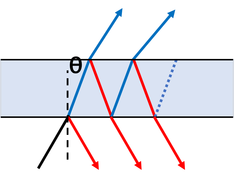
Interference based filters consist of several carefully designed layers that selectively transmit wavelengths based on the interference effects that occur between the incident and reflected waves at the layer boundaries.
Most optical filters are interference filters, which are based on the principle of the Fabry-Perot interferometer (or etalon). These multi-layer devices are made of microscopically thin layers of material composed of varying types of glass or fused silica, with each having two reflecting surfaces or mirrors. The peak wavelength transmission corresponds to the resonance of the etalon (Fig.1). Multiple etalon layers of different optical path lengths are included to transmit a broader range of wavelengths, and the bandwidth of a filter is determined by the number of these layers. The use of interference-based filters in microscopy has increased substantially due to the high level of selectivity and transmission when compared to glass counterparts.
Acoustic
Acoustic based filters consist of a birefringent crystal; application of an oscillating radio frequency (RF) alters the refractive index and thus diffraction properties of the crystal. Changing the RF changes the wavelength of light that is diffracted, enabling rapid wavelength tuning.
Acoustic based filters, also known as acoustic-optic tunable filters (AOTF) are increasingly being incorporated into microscopy applications as they do not suffer mechanical constraints, speed limitations and can easily accommodate a lot of different laser systems and output wavelengths. These are generally restricted to well-collimated light sources. Several limitations exist with AOTFs, including their inability to work with sub-450 nm wavelengths, and that thermal effects can modify the refractive index of the crystal until stability is achieved.
Types Of Filters
The three most common types of filters used for color selection in fluorescence microscopy are excitation filters, barrier filters and dichroic beam splitters. In modern microscopes, these are typically interference-based filters.
- Excitation filters permit the passage of specific wavelengths of light (excitation wavelengths) on the way towards the specimen.
- Barrier/emission filters attenuate the excitation wavelengths and permit only the selected emission wavelengths to pass towards the eye or the detector.
- Dichroic mirrors are specialized filters that consist of a thin piece of coated material (often UV-grade fused silica) set at a 45° angle. This coated material is designed to efficiently reflect the excitation wavelengths and transmit the emission wavelengths with efficiencies of up to 95%.
Filters can also normally only pass either short wavelengths, long wavelengths, or a band between long and short wavelengths and these are termed and defined as follows:
- Long pass (LP) filters transmit wavelengths greater than a certain wavelength, described by wavelength at 50% of peak transmission.
- Short pass (SP) filters transmit wavelengths below a certain wavelength
- Bandpass (BP) filters transmit wavelengths of light between two different wavelengths, giving a band of transmitted wavelengths.
LP, SP and BP filters are described further in Fig.2.

Although historically SP and LP filters were used, most modern filters are BP filters due to the additional control over wavelength. Most fluorophores in fluorescent microscopy have very well-defined bands of excitation and emission profiles, so BP filters work very well for selectively permitting the passage of excitation light and emission light for improved signal generation and collection.
Filter Sets
A common issue with filters is knowing how to orient them in the light path. For simplification and ease of use, filters are usually matched and combined to make a filter cube (Fig.3). Filter cubes, therefore, consist of an excitation filter, a dichroic and a barrier filter correctly orientated in order to permit fluorescence imaging of specific wavelengths of light, whilst removing any interference or artifact from other sources, such as the excitation light.
Optical filter sets that are used in fluorescence acquisitions are designed around the major wavelengths used in fluorescence applications, which is based around the most used fluorophores. For this reason, cubes are often named after the fluorophore they are intended for imaging, such as DAPI (blue), FITC (green) or TRITC (red) filter cubes. These filter cubes are placed in the light path and filter the light selectively to permit high contrast fluorescent imaging. Filters inside filter cubes from different manufacturers are most often not interchangeable.
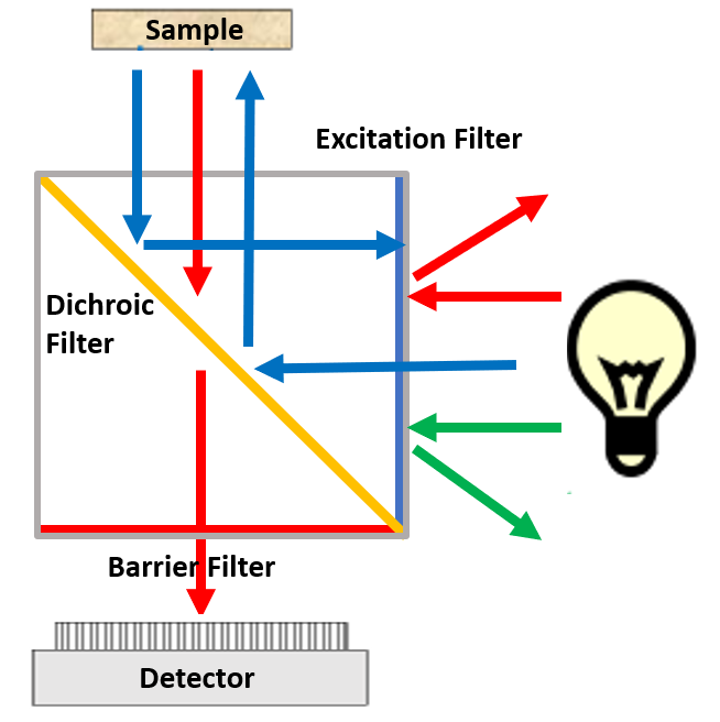
During a fluorescent acquisition, light of a specific wavelength is generated by passing multispectral light from a light source through the excitation filter, selectively passing the desired excitation wavelengths. Wavelengths that pass through the excitation filter then reflect off the surface of the dichroic mirror, which is tilted at a 45° angle to the excitation light, through the objective lens to the sample, exciting fluorophores that have an excitation spectrum correlating to the wavelength of the light.
Following excitation, fluorophores will emit light of a longer wavelength when compared to the excitation light, this emission light is gathered by the objective lens, and passes back toward the dichroic mirror, where it can pass through (due to the longer wavelength). The unwanted scattered excitation light is reflected towards the light source. The emission light, prior to hitting the detector, is then filtered by an emission filter that removes any residual unwanted light (such as autofluorescence).
These highly efficient filter sets provide maximum attenuation of excitation light in the detection pathway, in parallel with the successful capture of as many emitted photons as possible. High detection efficiency enables a corresponding reduction in illumination level and thus reduction of phototoxicity to the specimen.
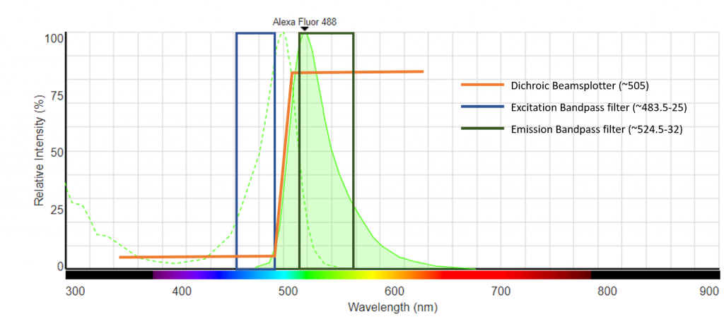
An example spectral diagram of an Alexa Fluor 488 filter cube is shown in Fig.4. The excitation and emission spectra of Alexa Fluor 488 are shown, and the corresponding excitation, emission and dichroic filters that are specifically matched for imaging this fluorophore are shown.
As well as individual filter sets, there are also dual- and triple-band filters available which allow simultaneous imaging from multiple fluorophores. For example, the DAPI-FITC-TRITC filter combinations allow for the simultaneous detection of these or other fluorophores that have similar spectral characteristics. Care must be taken however to ensure that the excitation of any included fluorophore overlaps as little as possible with the transmitted emission wavelength range of another – this would lead to what is known as ‘crosstalk’, where excitation light unintentionally reaches the detector.
Naming Of Filters
There are a lot of unusual conventions for filter names that can be confusing. Likewise, many manufacturers adopt their own nomenclature. As mentioned, the three main classes are excitation filters, emission/barrier filters, and dichroic filters, but filters can also be categorized as SP, LP or BP. Commonly, filters are referred to by these characteristics and the wavelength where they switch between transmission to reflection.
The identifications of different filter types and their nomenclature are as follows:
- Excitation filters: Ex or X may be used. Excitation filters include blue glass (BG) or ultraviolet glass (UG)
- Emission/barrier filters: BA or M may be used. Emission/barrier filters include yellow glass (Y or GG) or red glass (R or RG).
- Dichroic filters: can also be named beamsplitter (BS), chromatic beamsplitters (CBS), dichroic mirror (DM), teiler kante (TK, German for edge splitter), farb teiler (FB, German for color splitter) or reflectance short pass (RKP)
In addition, in order to differentiate between shortpass, longpass and bandpass filters, filters are denoted SP (or KP from kante, German word for edge), LP (or L) and BP (or B) respectively.
Often filter names include numbers too. As the most common unit for describing filters the wavelength of light in nm, this is used to describe the filters properties. For a BP filter the central wavelength (CWL) at 50% of peak transmission is used, often followed by bandwith. For a LP filter, the number used would be the ‘cut-on’ wavelength. For a SP filter this would be the ‘cut-off’ wavelength, which is the point where the filter switches from transmitting to reflecting and is transmitting 50% of the peak transmission.
To give an example of this: A hypothetical BP filter is a combination of short pass (550 nm) and long pass (500 nm) would individually be termed SP550 and LP500, but when describing a BP filter combination, it would be labeled as BP 525d25. This indicates a bandpass centered at 525 nm with 25 nm transmission permitted to either side.
Other Types Of Filters
There are other types of filters that are available for microscopy applications. The following list indicates their name and uses:
- Neutral-density (ND) filters: used to reduce the intensity of illumination light across a broad spectrum, without modifying the range of wavelengths available. They have constant attenuation across a range of visible wavelengths, and thus specifically reduce light intensity through reflecting or absorption. ND filters are available in multiple densities and materials and can be stacked to increase optical density and increasingly attenuate light intensity.
- Wedge filters: the thickness changes continuously, or in steps through the filter in the shape of a wedge. These are also known as linearly variable filters (LVF). It is used for applications such as hyperspectral sensors.
- Polarizing filters: polarize light either linearly or circularly. This can be used for polarized light microscopy, which a label-free method to examine birefringent (double refracting) anisotropic materials.
- Infrared (IR or heat) filters: either selectively block or transmit IR light. Many IR filters are used to prevent unwanted heating due to IR light. Illuminator lamp houses often incorporate an infrared light suppression filter. Near-infrared (NIR) imaging is powerful because tissue transmission is higher at longer wavelengths, ideal for applications such as small animal imaging. NIR filter sets are available for this type of imaging.
- Ultraviolet (UV) filters: either selectively block or transmit UV light. Making filters for the UV region of the electromagnetic spectrum is difficult, but new coatings using ion beam sputter technology using newly developed coatings now offer filters for the 250–320 nm range.
- Didymium filters: made of didymium glass to increase the intensity and saturation of red objects. This helps to prevent the washed-out problem that some colored stains give. They are often used with histopathological staining to enhance dyes such as eosin, fuchsin, and methylene blue.
- Yellow filters: fine-tune the color balance of tungsten and halogen microscope light sources for colour photomicrography. The yellow filter can also be helpful for metallurgical microscopy applications to identify failings in metal structures.
- Ground glass filters: placed over an illuminator to give a more even and diffused light. These are often used with tungsten light sources.
Summary
The modern microscope forms a central tool in scientific research and a lot of effort is directed towards maximizing the information gleaned from microscopy experiments. A critical part of microscopy is ensuring that a sample receives the correct illumination light, to ensure a fluorophore is excited efficiently and the largest number of photons are emitted. Not only this, but also to ensure that as many of these photos are captured as efficiently as possible, whilst simultaneously removing unwanted light and minimizing sample exposure and thus limiting fluorophore destruction.
Filters provide a means of efficiently filtering the light that passes through the system, mostly in the form of fluorescent filter cubes. These cubes are specifically designed for one or several fluorophores of interest and are an essential component to high-quality fluorescent imaging. Ensuring that the correct combinations of filters are incorporated into the system (and in the correct place) can maximize image quality and minimize specimen damage. Likewise, other types of filters are often incorporated into microscopes based on specific individual needs. These can include beamsplitters to permit imaging with multiple wavelengths simultaneously, polarizing filters, permitting polarized light microscopy, ND filters reducing multispectral light intensity, filters to remove harmful IR or UV rays as well as other filters used to enhance the image quality such as didymium filters and yellow filters.