
Introduction
Life is full of color, and capturing an image that replicates human perception of color is an important, and sometimes challenging, aspect of both everyday life and scientific research.
Although many cameras, such as phone cameras, video cameras, and commercial digital cameras, produce color images, a large portion of scientific research is carried out using monochrome cameras. Monochrome cameras capture only the intensity of light and not its color, yielding greyscale images that may be subsequently false-colored digitally.
Scientific color cameras are most often used in fields such as life sciences to document observations, particularly in histology and pathology, where samples of cells or tissues are inspected to understand health and diagnose disease. These types of samples require color imaging as tissue and cellular samples often consist of thin, transparent or semi-transparent sections devoid of significant contrast alone.
Since camera sensors alone cannot ‘see’ different colors, to capture color images, cameras must use a mechanism to separate the red, green and blue color components of the light. Standard monochrome camera sensors used in scientific imaging can be modified to capture color images.
There are different methods available that permit scientific color imaging, each of which relies on the addition of components, typically during manufacture, to permit imaging with red, green and blue. The important thing to remember is that all three colors must be acquired per frame, so each method is generally accompanied by a trade-off by a factor of three in different aspects of camera performance.
In this technical note, we will discuss why color imaging requires a sacrifice by a factor of three, how color imaging is accomplished and how to best select the right color imaging technique for your desired application.
What Is Color?
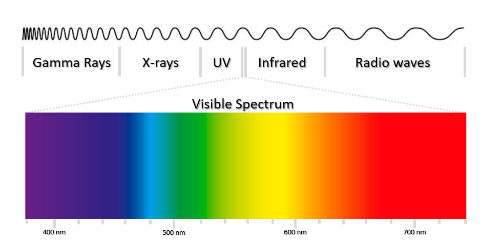
To understand color imaging, it is first essential to understand visible light. Visible light consists of two major components, wavelength and amplitude, which represent color and brightness respectively (Fig.1). White light contains all the wavelengths of visible light at approximately equal intensities, whereas light sources that appear only blue or only red consist of mainly the wavelengths corresponding to these regions.
A color image is a digital image that includes intensity information for different colors at each pixel. Although color is a continuous spectrum, colors are often described using the red, green, blue (RGB) model. The RGB model is representative of how human perception of color works by using three different types of cones in the eye that are sensitive to red, green and blue. Combinations of these three primary colors can be combined to create a wide range of colors seen in everyday life. This model is also used for digital cameras, monitors and image file formats.
What Gives Rise to Color?
Objects appear in color due to their interaction with the different wavelengths of light. The interactions that can occur between light and matter are broken down into absorption, transmission and reflection.
When objects are perceived as a color (i.e. blue) it is because they are reflecting or transmitting blue wavelengths of light towards our eyes and absorbing the other wavelengths (i.e. green and red).
There are three main aspects of color imaging:
- Shining light towards a sample
- The wavelengths of light interacting with the sample to different degrees based on local properties
- The detection of the reflected wavelengths of light from the sample (red, green and blue components)
The light used in color imaging is normally white light. The white light is directed towards a sample and will interact with the sample. The sample itself will contain many atoms and molecules and each will have associated electrons. If the light has a wavelength that matches the vibrational frequency (resonance frequency) of the electrons, then that wavelength will be absorbed and converted into vibrational and thermal energy. As different atoms and molecules have different natural vibration frequencies, they will selectively absorb different frequencies of visible light.
Likewise, those wavelengths that do not match the vibrational frequencies of the atoms and molecules then the wavelengths of light will either pass through the material and be transmitted, or they will be reflected or scattered. This interaction, of either absorption, transmission or reflection decides which light waves are directed towards our eyes, or a scientific camera, determining the color that an object will appear. If many wavelengths are transmitted, then the object will be transparent, whereas if they are reflected they will appear opaque.
Once the light has interacted with the sample, the light reflected or transmitted can be detected by a digital camera (or our eyes). Once acquired, the three different color channels are recombined to give a full-color image, where each pixel has an RGB intensity value, which together can make any combination of visible colors.
Staining Methods For Color Imaging
Many thin sections or samples in biological imaging are devoid of color. To aid biological research and improve contrast, samples can be stained with dyes that change the absorption profiles of structures within the sample that the dye binds to. This leads to the transmission and reflection of different wavelengths and therefore modifies the contributions in the red, green and blue channels and intensities, highlighting various cellular architecture.
Staining requires a dye that binds to certain components of the cells, giving them contrast compared to the unstained (or counterstained) background. This staining can either be selective and specific, i.e. for chemical groups, or can be non-specific, staining most of the cell. Often staining regimes include a specific stain, followed by a non-specific counterstain. The intensity and appearance of stains can be quantified following imaging, which can be used to identify subtle changes not detectable to the human eye.
This forms the basis of many diagnostic or monitoring methods. In histopathology, differential staining patterns of samples can aid disease diagnosis based on the organization (or lack thereof) of the cells and can highlight abnormalities such as changes to nuclear or cytoplasm morphology that occur during cancer.
Types Of Color Cameras
At the most basic level, color cameras work like conventional monochrome cameras, meaning that incoming photons interact with light-sensitive pixels during exposure, irrelevant of wavelength or color, and the intensity of each pixel is read out as a digital image. Monochrome cameras, without additional components such as filters, do not differentiate between different wavelengths of light.
When RGB images are desired, the incoming white light must be separated into its component colors, each of which is independently measured. There are four main methods of achieving this:
- Using filter array masks on the detector itself splitting up the detector into dedicated red green and blue pixels
- Using moving filters in the light path and acquiring separate images
- Using three different sensors, one for each color
- Using a fast switching light source
These methods of converting a standard monochrome camera into a color camera are detailed in the next sections.
Color Filter Arrays
Color Filter Arrays (CFA) are the industry standard for coloring imaging. CFAs are used to mask different pixels on an array. The most common type of CFA is the Bayer filter array, which arranges pixel filters in a GRBG pattern (2×2), as shown in Fig.2 repeated across the entire detector. In this method, each pixel corresponds to a colored filter and is dedicated to imaging this color only.
At each pixel, the filter prevents the passage of light that is not of the desired color, so a pixel dedicated to measuring red light, only permits red wavelengths to pass through. Following passage through the filter to the dedicated pixels, photons are detected by the light-sensitive region as in conventional scientific camera light collection.
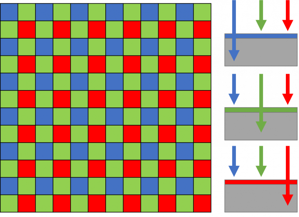
This Bayer filter seen in Fig.2 has twice as many green masked pixels as red or blue. This is done because the human eye is more sensitive to green light, and therefore green pixel redundancy produces an image that appears less noisy and has finer details than could be accomplished if each color were treated equally.
As the exact location of each filter is known, following the acquisition of the red green and blue images, an algorithm can interpolate between pixels to create an image that has RGB intensity values. However, as each pixel is only actually acquiring information for red, green or blue, this means 2/3 of the pixel intensities are interpolated, decreasing the resolution by a factor of 3.
Sensitivity is also affected, as only a fraction of the available camera pixels can be used to detect light of a given wavelength. Only 25% of the pixels of the sensor can detect red or blue light, and only 50% for green.
The advantage of using a Bayer filter is speed. When using the Bayer filter cameras, only one acquisition is required and only one sensor is needed. This is advantageous as all colors are acquired at the same time. Imaging is, therefore, faster than acquiring three sequential images and does not risk loss of temporal information or simultaneity if imaging live or at high speeds. Additionally, the simplicity and cost-effectiveness of having a single sensor and no moving parts make this the most popular method for color acquisition.
The major downside to this method of color image capture is the loss of resolution and sensitivity due to the interpolation and binning of neighboring pixels which is unavoidable due to the pixel masking. This can also lead to interpolation errors and loss of information. Another disadvantage is that CFAs make use of absorptive dye filters, which are inferior to dichroic filters in terms of color purity.
Moving Filter Wheels
An alternative to masking pixels with a Bayer filter is to use multiple acquisitions that are taken individually. The main option here involves the use of moving filters to sequentially acquire each channel image.
The method of moving filters in the light path with a standard monochrome camera permits sequential filtering for red, green and then blue light imaging in the light path. Once all three acquisitions are complete, the three images are recombined to make the full-color image, with each pixel having a RGB value (Fig.3).
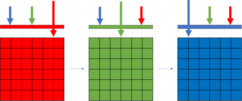
This sequential acquisition of each channel allows the entire sensor area to be used so that all available pixels are collecting either red light, green light or blue light. This method permits a higher resolution than using Bayer filters as intensities for each color image is acquired at each pixel. Therefore, no information is lost, and no interpolation is necessary to permit the images to be combined.
During sequential acquisitions, it is sometimes thought useful to modify the exposure time, based on the detector and the wavelengths being imaged, offering additional flexibility compared to the CFA method. Each pixel in the CFA is subject to the same exposure time, as they are acquired together, but there is no such limitation with this technique.
However, there is a big drawback in the moving filter method, in that the time taken to switch the filters within the system reduces the speed of imaging by 67%. If speed is not important then this could be the best method, however where speed is important it would lead to loss of temporal resolution. Not only that, the images would be taken at subtly different times as they are acquired sequentially. Due to the various mechanistic issues with moving filter wheels, these are not regularly integrated into consumer-grade cameras.
Three Cameras Or Sensors
There is another alternative that does not require any filter switching nor loss of FOV or resolution. This option involves the use of three separate cameras or three separate sensors within a single camera.
In this case, each camera or sensor is dedicated to imaging a specific color (either red, green or blue). In this set up, following sample illumination, a beam splitter can be used to separate the light into three separate beams (Fig.4). The beams then pass through various dichroic filters, separating the light into narrow bands which can then be detected on the respective camera or sensor.
One method of incorporating three sensors in one camera can be based on using silicon sensor stacks of multiple photodiodes to detect each color at each pixel (Fig.4B). A three-sensor stack relies on the wavelength dependence of photon absorption, and the charge is collected separately at different depths in the silicon, however, this technique is more challenging to perfect and still under development.

This method offers a 1:1 color ratio which means that 3 sensors offer the highest image quality, whilst maintaining the whole field of view for each color alongside no loss in speed for filter changing. The image quality is also improved due to the use of dichroic filters, which are generally of higher quality than those used in the Bayer masking. This also means that no interpolation is necessary, as no pixels are lost, which improves sensitivity and resolution.
The most obvious downside of this set up is that, due to the need for three separate sensors/cameras, they also tend to cost significantly more money (roughly three times more) than other color camera solutions. These types of camera should be picked when an exact RGB value and the best image quality is required.
Fast Switching Light Source
A new solution has recently become available in the form of the fast switching light sources which circumvent some of the issues related to errors in interpolation, loss of resolution, speed trade-off and increased cost.
A light source that can switch between red, green and blue excitation light quickly can be combined with a monochrome camera to permit color imaging. These types of light sources often include solid-state LEDs with a fast color-switching mechanism included that permits that acquisition of RGB channel images. The acquisitions are generally captured in a high-speed sequence through an internal camera trigger, allowing high-speed image acquisition without the need for moving filters.
This method removes the variance associated with moving components such as filters and permits the perfect registration of pixels in the image across a large field of view. The light source method, therefore, improves upon the speed, sensitivity, and precision of color transmitted light microscopy. The light source also offers a cheaper alternative to using three cameras, whilst maintaining the advantages offered by this method.
However, the light source still requires time to switch the light sources, so although faster than switching color filters, it still is slowed from the potential maximum rate by a factor of 3 to incorporate this switching mechanism.
Summary
The relative advantages and major disadvantages of each of the color imaging methods are summarized in Table 1. The correct solution for the individual application will vary depending upon which factors are most important for the imaging system and requirements.
Table 1: Summary of the potential mechanisms for collecting color images and their main advantage and disadvantage.
| Camera Type | Mechanism | Advantages | Disadvantages |
| Bayer Filter Array/Mask | Masking of pixels | Fast, cheap | 33% resolution and sensitivity |
| Moving Filters | Filter wheel | Max resolution | 33% speed |
| Three Sensors/Cameras | Separate sensors for RGB | Max resolution and fast | 3x price |
| Switching Light Source | Internal trigger LED | Max resolution | 33% speed |
The acquisition of color images is an essential aspect of many biological imaging investigations. There are a few distinct methods that can be employed to obtain these three-color images, each with associated advantages and disadvantages that are presented in Table 1. Generally, there is a trade-off either in the resolution obtained in the images, the time taken to acquire the images or in the cost of the system.
The cheapest method remains to use a dedicated color imaging device that contains a Bayer mask array inside. If the camera is likely to have a dual purpose for fluorescent imaging, or if the loss of spatial resolution is more important than collecting simultaneous images it may be worthwhile to buy a monochrome camera and use a mechanical filter wheel to sequentially acquire the images.
The highest quality data will be obtained when collecting the images with a three sensor/camera option that permits fast, simultaneous imaging of each channel with the full field of view of the sensor, requiring no interpolation. However, this option will be the most expensive as the cost is effectively three times greater due to the cost of the sensors, and the range of commercially available cameras that implement this technology is poor.
Alternatively, to achieve a balance of resolution, spatial and temporal, as well as minimizing costs and maximizing image quality and facilitating easy realignment, an internally triggered fast switching LED light source linked with a monochrome camera may offer the best of both worlds for color imaging applications and maintaining the advantages of a scientific monochrome camera for fluorescence imaging.