
Introduction
In microscopy, we aim to produce a sharply-defined, magnified image of our sample in our detector or our eyes. The sample requires illumination for us to see it – but how do we avoid simply seeing a sharply-defined, magnified image of the LED, bulb filament or arc lamp of our light source? Instead, we require even, uniform illumination of our sample, free from structures and patterns, no matter what light source we use. The optical method for achieving this was invented by August Köhler (Köhler 1893). This method, called Köhler illumination, underlies the common modern illumination methods in brightfield, phase contrast, darkfield and epifluorescence imaging.
The need for Köhler illumination, and the mechanism by which it is achieved, are best understood through seeing a microscope as a series of simple lenses. This article will introduce the behavior of a simple lens, and then explore the mechanism, optics and common practice of Köhler illumination.
How Is An Image Formed With A Lens?
At its simplest, a microscope may be seen as a series of simple (aberration/defect-free) lenses. The behavior of a single lens is illustrated in Fig.1.
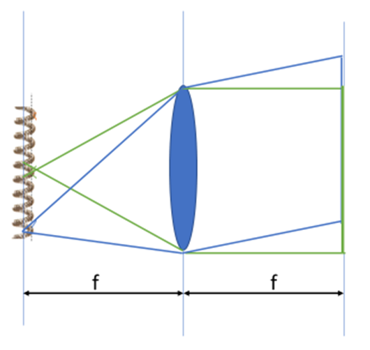
Light from a point on the left (the light source filament in Fig.1) expands in all directions. If emitted at a distance from the lens equal to the lens focal length, it is organized to a collection of parallel rays upon exiting the lens. While only the direct, central ray and a large angle ray are illustrated, every ray in the collection angle of the lens behaves similarly.
When propagating as parallel rays, the image of the object on the left would not be visible were we to observe those rays. The effect of this is that the image will be blurred and mixed, and structural information about the object (i.e. the details in a biological sample, or the filament in a lamp bulb) will be unrecognizable. To restore the parallel rays to a real image, a second lens must re-focus the parallel rays onto a second plane.
The Optics Underlying Köhler Illumination
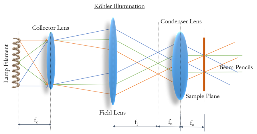
The predecessor to Köhler illumination was critical illumination. This method used two lenses as discussed above to produce a magnified image of the light source at the sample plane. This provided effective illumination, however, an image of the light source was superimposed over the sample. Köhler’s innovation was to add an additional lens to the illumination light path, which converts the image into parallel propagating light waves, with visible structure no longer recognizable.
With this additional lens in place, one can see the different points from the illumination source, as illustrated by the red, green and blue lines in Fig.2. This means that the same region of the sample is illuminated from different angles, scrambling the filament/light source structure. This means that the illumination of the sample will be highly uniform and free of any structures from the light source.
Illumination Control Using Köhler Illumination
Köhler’s optical design also allows for the control of: the illumination field of view, the power delivered to the sample, and the effective illumination numerical aperture (NA).
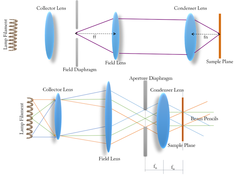
Control of the illumination field of view is obtained by placing an adjustable aperture in the light path to the left of the field lens, as demonstrated in Fig.3. An image of the diaphragm is transmitted by the field and condenser lens, with the image of the condenser formed at the sample 4 focal lengths (4f) away. This 4f optical configuration underlies modern infinity-corrected microscopes.
In addition, placing this aperture to the left of the condenser lens allows control of the range of angles being transmitted to the sample, thus controlling the NA and the resolution. It also controls the light density/power within the field of view, as opening or closing the aperture blocks or allows light from positions farther from the center of the light source. Fig.3 illustrates the function of the aperture.
Setting Up Köhler Illumination On A Modern Microscope
Most microscopes can be used in either transmission/trans-fluorescence mode, where the light travels through from the light source through the sample to the eye or camera, or in reflectance/epi-fluorescence mode where the light delivered through the objective follows the same path back before being deviated off to the eye or camera. For typical microscopes, Köhler illumination setup is not adjustable in the epi-fluorescence path, with the exception of centering the light source and its reflection within the optical plane.
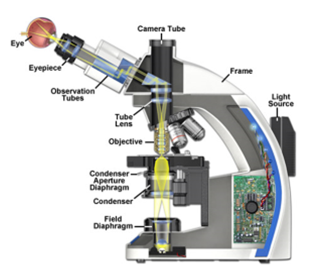
In transmission imaging, the components of Köhler illumination are more adjustable and therefore more likely to need correction with everyday microscope use. A common approach is presented below, with some reference to the underlying optical considerations presented. An illustration of the location of the various components on an example upright microscope is illustrated in Fig.4.
Stepwise Instruction For Setting Up Köhler Illumination
(Adapted from common practice and the Zeiss.com Köhler webpage)
- Turn the microscope on and focus the image of the sample to be as sharp as possible to eye or camera.
- Find the control of the field diaphragm on the illumination path. Closing this should provide reduced field of illumination with the sides of the iris visible. These edges should be sharply in focus.
- Focusing the condenser. There is a focus control/knob on the microscope body that adjusts the position of the condenser. Using a partially closed field diaphragm, focus the condenser such that the edges of the diaphragm appear sharp in the image. It is possible with high magnification lenses that the FOV of the condenser will be greater than the FOV of the objective. If that’s the case, try with a lower magnification objective; the condenser focus should be close to identical with most objectives focused to the same spot.
- Center the condenser. Most condensers have positioning control in X and Y, often with thumb screws. Open the field diaphragm so that one corner is touching the visual edge of the field. If all the other corners are touching to the same extent, the condenser is aligned. If not, move the set screw to better position the image of the field stop to the center and try again. It can take some back and forth but is relatively easy. If turning one screw doesn’t move the image, stop. It’s possible the screw is too far out and no longer putting force on the condenser, or too far in with no room to go farther. Once the condenser is centered, open the field stop until it illuminates the area to be imaged.
- Adjust the aperture diaphragm for optimal imaging. Having the aperture diaphragm open between 60 and 90% of possible usually provides the most contrast and highest resolution. The only problem is the aperture diaphragm is not able to be imaged directly through the microscope eyepieces or to a camera as its in an intermediate plane in the optical path. Some vendors integrate a “telescope” or Bertrand lens option which changes the optics so that the aperture can be imaged to the eyepiece. Otherwise, remove an eyepiece and look down the tube from about 8-12 inches away. Adjusting the aperture stop should be seen opening or closing in the field of view through the telescope/missing objective tube. Once you’re able to see the aperture stop adjust it to the proper size and return the eyepiece or remove the Bertrand lens for normal imaging. You should now be ready to image.
Common Problems In Setting Up Köhler Illumination
Setting up Köhler illumination becomes second nature with practice. One common condition can confound most beginners and even some experts is the adjustment of the aperture diaphragm. The appropriate size to match a low magnification low NA lens may be sufficiently closed to essentially extinguish all light transmittance through higher NA, usually high magnification lenses. It is, therefore, a good idea to check the aperture diaphragm when changing to higher NA objectives.
Conversely, the aperture diaphragm can be opened too wide, but this is less likely to cause problems given the high-quality engineering of the light paths in modern microscopes. This can allow stray light rays from unexpected directions to illuminate the sample and reduce contrast or introduce glare.
Summary
Köhler illumination is critical to removing illumination source structure from the image of the sample. The correct application of Köhler illumination provides the best possible contrast in both brightfield, phase contrast, and fluorescence techniques.
References
Köhler, August (1893). “Ein neues Beleuchtungsverfahren für mikrophotographische Zwecke”. Zeitschrift für wissenschaftliche Mikroskopie und für Mikroskopische Technik. 10 (4): 433–440.
Koehler, August (1894). “New Method of Illumination for Photomicrographical Purposes”. Journal of the Royal Microscopical Society. 14: 261–262.
Lenstotek.com webpage on Köhler illumination http://www.lenstrotek.com/archives/457
Zeiss.com webpage on the basic optical train of a microscope http://zeiss-campus.magnet.fsu.edu/articles/basics/opticaltrain.html
Zeiss.com webpage on Kohler illumination http://zeiss-campus.magnet.fsu.edu/articles/basics/kohler.html