
Introduction
Optics are elements that alter the travel of light to achieve some effect. In microscopy, these effects commonly include the magnification of the light coming from the sample, the manipulation of light pattern or color, and the interaction of light with itself.
In this note, the interaction of light with matter leading to refraction, the ability of light to be focused by a lens, and the manner in which a lens or collection of lenses gives magnification are presented.
Refraction
Light transmission through a material is most relevant to optics. Light travels as a wave, though it is most commonly detected as if it is composed of particles (photons). The speed of light in a vacuum is constant, but light slows when it travels through materials other than vacuum. This slowing is determined by the refractive index (n) of a material. The refractive index indicates the relative speed of light as it travels through a material compared to that in a vacuum.
As the light slows, the peaks and troughs become more compressed, so that the effective wavelength changes and the light ray can change direction if hitting the interface at an angle. This is known as refraction and is illustrated in Fig.1

Essentially, the light ray cannot be stopped or broken, so it has to change direction. This refraction is always towards the optical center (shown by the black line in Fig.1).
Lenses
The fact that light is refracted and changes direction when entering a denser medium is the principle behind the lens when light moves from air to glass and can be manipulated by the shape of a lens.
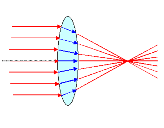
Lenses Focus Light
As illustrated in Fig.2, glass lenses can focus light due to their greater refractive index than air (n = 1‑5‑1.6), and have a curvature to their surface that increases symmetrically out from the center. The uniform rays of light enter the lens and are deviated more if they enter the lens farther from the center due to the increased local curvature. Light rays entering the center of the lens do not change direction, even though they also slow, indicated by the shift to blue, in the glass. The exit from the glass also deviates the light ray, but to a smaller extent as the refractive index is lower. The position of the focal point f, where all the light rays cross, is dependent on both the refractive index of the lens material and the curvature of the material away from the center. Lenses can be made of different materials and in different shapes in order to manipulate light in a variety of ways.
Lenses Magnify Light
Light entering a lens can be focused and subsequently magnified. As illustrated in Fig.3, single-lens magnification can be achieved by placing the sample and the detector at positions greater than the focal distance away from the lens.
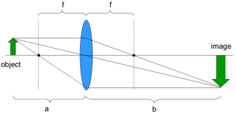
The magnification is simply distance b divided by distance a. This system has worked since the first magnifying glass and only runs into limitations when the samples are too thick.
Modern Microscope Optics
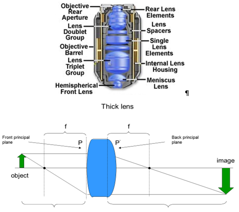
Current microscopes image in a much different manner than a simple single lens magnification system. The first obvious difference is that objectives look nothing like magnifying glass lenses, and are specified with their magnification, not their focal length.
A real lens or objective is too complicated to treat like the thin lens in Fig.3. The concept of principal planes, positions at which light focuses a distance f beyond allow thick complicated lenses to be modeled as a simple thin lens. For a lens designer, the arrangement of all the optical elements in the objective is critical but the ability to treat the space in between the principle planes as an “empty box” greatly simplifies the application of thick lenses and objectives.
Objectives specify a magnification, but lenses are commonly described by focal length. Modern microscopes combine the objective with a second lens hidden in the microscope body, the tube lens. This tube lens allows for advanced light manipulation techniques, such as infinity-corrected imaging, as seen in Fig.5.
The sample or object is placed at the focal plane in front of the objective. This means that the distance b at which the image is formed is at infinity. However, the tube lens takes these non-converging rays from the objective and refocuses them to an image four focal lengths (this is also known as 4f imaging), plus the gap between the principal planes, away from the sample. Magnification in this system is defined by the ratio of focal lengths of the tube lens and objective.
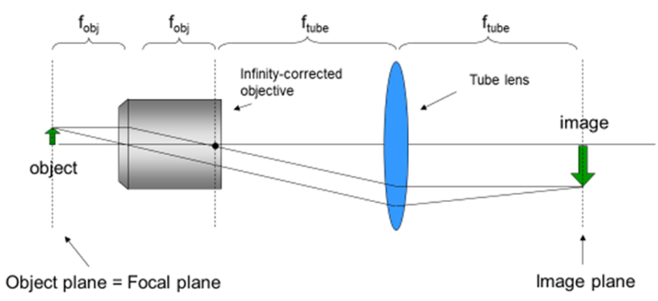
This approach provides several benefits. A major one is that magnification is equal at positions above and below the focal plane, unlike with single-lens imaging. Slight changes in the objective positions do not change the effective magnification or the position of image formation. Several imaging techniques such as fluorescence and phase-contrast microscopy put light modifying elements in between the objective and tube lens. In an infinity-corrected microscope, all the light rays are organized in parallel and strike any light modifying accessories at the same angle. This makes it less likely to distort the resultant image.
Aberrations
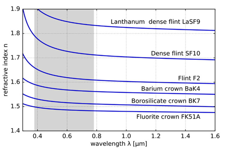
There are slight variations in refractive index depending on the color or energy of light and the type of glass, as illustrated in Fig.6. The dependence of lenses on constant wavelengths makes it difficult to focus light of different colors to the same spot. This is the cause of rainbows and the ability of prisms to split white light into a range of colors.
Chromatic aberration is where different colors from an object are focused on different points in X, Y and Z in the image. This is a common challenge for lens designers, who wish to avoid any aberrations. Accordingly, different standards of lenses have been implemented depending on the need to address chromatic and other aberrations.
Achromatic objectives focus red and blue light to the same spot and are correct against spherical aberration, where the light at near the center and near the edge of the lens is focused to different depths, for green light. These are the simplest lens designs and accordingly most inexpensive. These lenses are ideal for imaging with green light.
Fluorite, or Fluor, objectives are slightly more complex in design. They focus red and blue closer to green light and are spherically corrected for blue and green light. These lenses are often sufficient for general color imaging of samples.
Apochromatic lenses are highly complex and are corrected for chromatic aberrations for colors ranging from deep-blue through red. Depending on the manufacturer and model, they are spherically corrected for two or more colors. Commonly these lenses have the highest resolution due to having large numerical apertures.
Lenses may be designated with the prefix Plan in front of the lens type, Plan-Apochromat for example. Plan lenses are corrected to generate a flat field image from a flat sample. Simple thin lens imaging of a flat sample generates a curved image. Plan lenses correct for this distortion with more complex optical elements within the objective.
Summary
Lenses and other optical elements function because of the reduced speed of light in materials other than vacuum. The curved interface of the lens collects light rays and focuses them to a point at the lens focal length. Infinity-corrected (4f) optical paths underlie all modern microscopes and provide the most flexible and uniform imaging system to date. Objectives like other lenses can have issues with errors like aberrations. Different degrees of aberration correction are available depending on the design of the objective.
References
Abramowitz, M. 2003 Microscope Basics and Beyond, Olympus America, Scientific Division.
Abramowitz M and Davidson MW Olympus Microscopy Primer: Optical Aberrations https://www.olympus-lifescience.com/ru/microscope-resource/primer/anatomy/aberrations/
Lane, C 2018 Race to Refraction: The repeated discovery of Snell’s law. HOM SIGMAA 2018 Student Paper Contest Winners,” Convergence (May 2018) https://www.maa.org/press/periodicals/convergence/hom-sigmaa-2018-student-paper-contest-winners
Figures
Figures 3, 5 and 6 are from the Lecture notes of Dr. Jerome Mertz’s class BE517 Optical Microscopy of Biological Materials, given in the Biomedical Engineering Dept at Boston University. Some figures may have been modified for clarity.