
Introduction
Light microscopy offers a powerful technique for label-free imaging of biological samples such as cells. Label-free imaging is particularly well-placed for understanding more about cells as they are free of any modifications that could potentially alter structure, function or behavior.
However, standard light microscopy suffers from limitations of low contrast, as most native biological samples don’t absorb light (cells essentially being tiny transparent bags of water). Changes in the refractive index that scatter light can also reveal structure, but differences between the refractive index of cells, sub-cellular structures, and their surrounding matrix are often low or negligible. This leads to the low levels of contrast inherent to transparent specimens which limits light microscopy and other label-free techniques as research applications.
There are several imaging methods that generate contrast in these samples. One such method is phase-contrast microscopy. This optical technique converts differences in the optical pathlength or refractive index of the sample into shifts in the phase of light and uses these phase shifts to create contrast. Using subtle modifications of the regular brightfield optical path, phase contrast permits visualization of details such as intracellular organelles, in these otherwise featureless, unlabeled samples.
This article will introduce light phase and the mechanism of phase-contrast microscopy. Setting up the microscope to perform phase contrast imaging will be discussed as well as some of the applications and associated advantages and limitations.
What Is Light Phase?
Light waves can be mathematically described as a sine wave, as depicted in Fig.1 The amplitude of the wave corresponds to its intensity, which is interpreted as brightness when perceived by the eye. The wavelength of light, and its inverse, frequency, determines the energy and color. In Fig.1, the red wave is phase-shifted when compared to the blue wave.
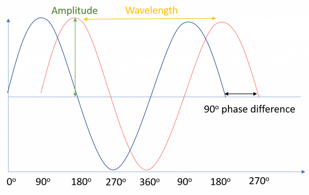
The phase of a wave at a given point in space or time refers to where along the sine wave the wave is at that particular point, i.e. is the wave at a peak, a trough, or somewhere in between? For example, two seagulls floating on the sea may be at different heights – the wavelength and maximum amplitude of the waves are the same in both cases, but the phase is different. Mathematically, we define phase in degrees or radians, relative to some reference point along the sine wave– for example, we could define the peak of the wave where the is seagull at its highest as 0°. The lowest point would then be at 180° (π radians), and the transition point between the two would be 90° (π/2 radians). The phase difference between the red and blue waves in Fig.1 is 90°.
Light waves can interfere with each other if they have the same frequency and well-ordered phases, with the result dependant upon the phase difference between waves. For example, waves that have the same frequency and are perfectly out of phase (180° phase difference) would align peak to trough, leading to destructive interference and resulting in 0 amplitude, the two waves perfectly canceling each other out. Likewise, waves that are perfectly in-phase align peak to peak (0° phase difference) and thus would constructively interfere, combining the intensities into a wave with double the amplitude.
What Is Optical Path Length?
Light moves through a vacuum at the speed of light (300,000 km/s). If the light is moving through a denser substance it moves slower, depending on the refractive index (RI) of the medium the light is moving through. The higher the RI, the slower the light. We could alternatively represent this delay as if the light has had to travel further at the same speed. This is the optical path length (OPL), which is given by the distance traveled through a substance, multiplied by its RI.
If two waves with the same wavelength start from the same point and take different paths before reaching the same point, there will likely be a difference in OPL. Unless this difference is a precise multiple of the wavelength, there will be then a difference in phase between the two waves. This means that phase differences in light from the same sample can be introduced by forcing some of the light to travel further. This is the concept behind phase-contrast.
Phase-Contrast Microscopy
Phase-contrast microscopy was first described by Dutch physicist Frits Zernike in the 1930s, for which he later was awarded the Nobel Prize in Physics (1953). Phase contrast is a technique that exploits the ability of some microscope samples to alter the OPL of light passing through it, adding contrast through the interference of light of different phases.
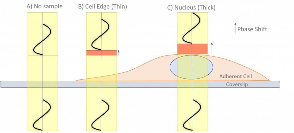
Transparent unstained samples (such as cells) do not absorb light and are called phase objects. When light passes through a sample area with no phase object, there is no significant change in the RI or OPL, so no significant diffraction occurs (Fig.2). This light that is not diffracted is often referred to as direct or zero-order light as it continues unmodified through the sample.
On the other hand, when light passes through an area of the sample with a phase object (such as cellular structures), small changes in the RI will diffract and scatter some light and cause changes to the OPL, depending on the thickness and RI of each structure. The thicker the structure, the greater the diffraction of the light.
The diffracted light is a small proportion of the total light that has passed through the sample. This diffracted light (that passed through a phase object) arrives at the detector out of phase with the direct light (that did not pass through a phase object). This small phase shift is not enough to cause significant interference between direct and diffracted light, which along with the poor absorption of transparent structures means there is little amplitude difference between areas where such structures are present and where they are not.
Phase-contrast microscopy is a method that manipulates this property of phase objects to introduce additional interference between the direct and diffracted. This technique transforms differences in phase into differences in brightness, increasing contrast in images of non-absorbing samples.
How Is Phase-Contrast Implemented?
There are two main issues when implementing phase-contrast microscopy: How to phase shift the scattered light or the direct light but not both, and how to get light with well-ordered phase to illuminate the sample. Light sources with a uniform phase didn’t exist before the invention of the laser (1960s).
It was known that constraining light through a small pinhole generated an expanding light wave with well-organized phase but at the expense of a great loss of intensity. This circular wave was easily converted to a flat wave with a lens. Phase-contrast compromises between light intensity and uniform phase by using a circular ring (annulus) of illumination. This annulus acted similarly to a ring of pinholes, with any particular direction around the ring having the same phase, even though the phase would vary irregularly around the ring.
To phase shift either the scattered or direct light, a phase-shifting optic (like a glass disk) is placed in the light path where it would predominantly affect the direct light. In Fig.3, a well-ordered light plane starts on the left. As the light hits the sample the phase and direction of the diffracted (solid lines to the right of the sample) and direct (dashed lines) light changes. The objective lens takes the scattered light and focuses it to ordered waves, while the direct light is focused to the optical center, where the phase-shifting material is placed. This brings the scattered light and direct light back into phase, allowing for the generation of contrast through interference upon arrival at the detector.
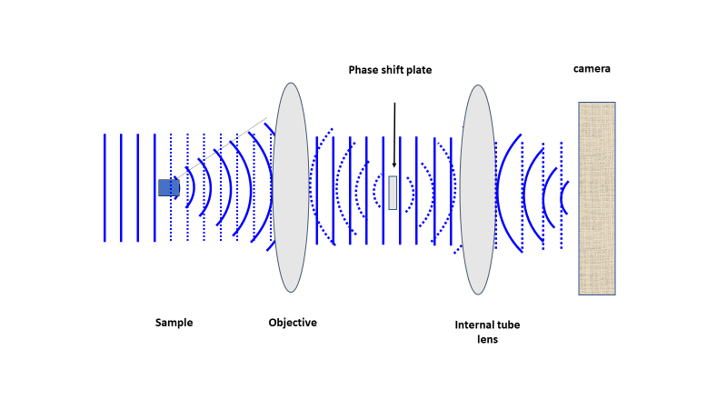
A phase-contrast microscope with annular illumination is depicted in Fig.4. Implemented in a modern infinity-corrected microscope, the phase-shifting ring is located at the objective rear focal plane. The two components required to convert a traditional bright field microscope into a phase-contrast microscope are the annular diaphragm placed in the condenser back aperture, and the optically matched internal phase plate. The phase plate is introduced into the light path at the rear focal plane, often permanently etched to one of the internal lens elements of the objective (such as the tube lens from Fig.3). This phase plate decreases the direct light to more closely match the intensity of the diffracted light, and thus further reduce the contribution of background light to the image.
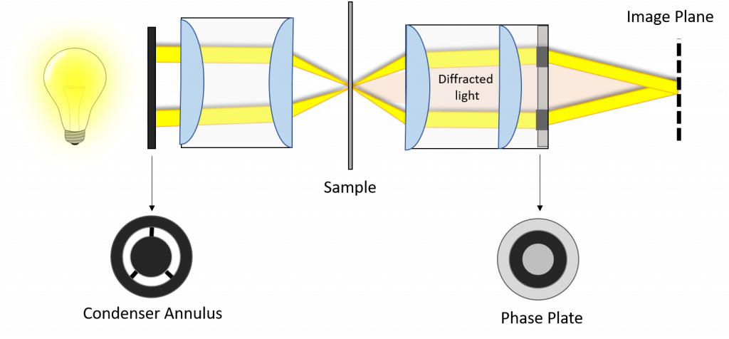
Light passing through the sample is refracted or diffracted due to features with different refractive indices, creating new optical paths. Almost all of these new optical paths will not pass through the attenuating areas of the phase plate but instead will pass through the non-attenuating center of the phase ring.
The wavefronts that are diffracted to varying degrees by passing through the specimen become superimposed over the shifted direct wavefronts in the intermediate image plane. With the 90° shift taken into account, the total phase difference is either close to 1 for a positive shift, leading to destructive interference, or to 0 for a negative shift, leading to constructive interference. Small changes in RI, therefore, lead to large changes in interference.
This leads to objects with a higher RI than their surroundings appearing dark on a bright background, or bright on a dark background depending on whether the technique is positive and negative phase contrast respectively. Positive phase contrast is the standard in modern microscopes, where the darkness of the object features increases with their refractive index, which simulates the effect of absorption to a viewer’s eyes.
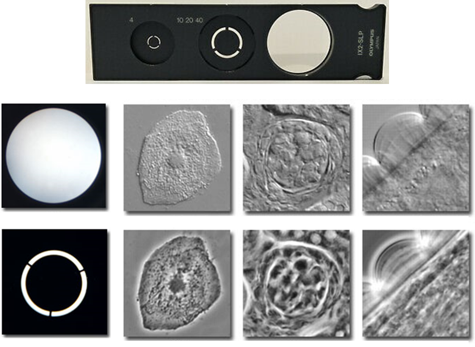
As objective numerical aperture and magnification increase, the phase plate width and diameter both decrease. Conversely, as magnification increases, the condenser annulus size increases. Thus, in order to achieve high-quality phase-contrast images, the correct phase plate and condenser annulus pair must be used and the condenser annulus must be properly centered such that the image of the annulus corresponds exactly with the position of the phase ring. Examples of these phase rings and the resulting image, when compared to non-phase techniques such as brightfield, can be seen in Fig.5.
Advantages and Disadvantages Of Phase-Contrast
Advantages
The major advantage of phase contrast is its ability to generate image contrast from materials that don’t absorb light, including cells and tissues in culture. Thin, transparent, colorless samples can contain details so fine that, even if absorbent, don’t show up well such as Cilia and flagella. But these same samples exhibit strong contrast when using phase-contrast. Using phase-contrast, therefore, allows identification of cellular structures and sub-cellular components such as the nucleus and organelles (mitochondria, Golgi, granules) with different densities. The ability to image these samples with high contrast and resolution, without the need for labels, is a highly advantageous property of phase-contrast microscopy.
Another advantage of phase contrast is the potential to combine it with other techniques, such as fluorescence microscopy to identify subcellular components through specific labeling. Combining multiple methodologies provides opportunities to understand greater levels of detail from a single sample, and provides new opportunities to glean additional information relating to subcellular structure and function.
Some samples will give rise to stronger contrast when using either positive or negative phase contrast methods. As an example, human red blood cells lack contrast in positive phase contrast but have high contrast when using negative phase imaging. Conversely, cancer cells visualized with negative phase imaging exhibit little contrast, but when viewing with positive phase contrast, the cell outline as well as internal components, such as organelles, exhibit strong contrast against the surrounding matrix. Understanding the most appropriate mode for a specific sample likely depends on the matrix (imaging media, growth media), the sample itself and their RI differences.
Disadvantages
A constraint of phase contrast is that it does not work well with thick specimens because phase shifts from areas below or above the focal plane contribute to the image giving rise to out-of-focus blur. Optical phase artifacts are also common, such as halos and shade-off contrast patterns which may be present in the images.
The halo effect is described by the appearance of a bright edge for positive phase contrast or a dark edge for negative phase contrast around large objects which obscure details. Halos form because small amounts of stray light diffracted light from the specimen can also cross the phase ring. This is not subject to the same interference in the image plane, which leads to a reversion in contrast and the appearance of halos at the boundaries of large objects. The haloes will be bright in positive phase contrast, and dark in negative phase contrast.
Shade-off is another issue present in-phase images. Shade-off refers to the intensity gradient present at large phase objects, which may be the brightest in the middle, resembling the surrounding matrix intensity. This will gradually reduce towards the edges of the object. The reverse is true in negative phase contrast shade-off, where the central area is dark, similar to the background. This is caused by the complicated relationship between pathlength and intensity, which is not linear.
Another issue with phase-contrast is contrast inversion. This is caused by the presence of objects with high RI objects next to objects with a lower RI, which will appear brighter instead of darker (for positive phase-contrast). This leads to the high refractive index objects appearing bright, rather than dark (in positive-contrast).
The configuration also has other limitations including the reduction in resolution of the optical system due to the restriction of the numerical aperture by the phase annuli. This can be restrictive if the resolution is a critical part of the imaging experiment.
However, the advantages that phase-contrast offers for biomedical and biological research greatly outweighs the artifacts or limitations of the technique, and the use of phase-contrast has revolutionized various fields of cell biology.
Summary
Phase-contrast is a technique that can be implemented on a traditional brightfield microscope with the addition of two components, matching phase plate in the condenser and condenser annulus, usually in a phase-contrast lens. When correctly configured, phase-contrast offers an excellent method to visualize otherwise transparent specimens that would be almost invisible on traditional brightfield imaging.
Phase imaging overcomes limitations inherent in absorbance imaging in visualizing subcellular components with high contrast without the need for specific labeling. Phase-contrast can also be used to compliment fluorescent microscopy due to the difference in their optical configurations.
Phase-contrast has some limitations, such as optical phase artifacts and non-linearity. Overall, the technique has contributed significantly as an optical imaging method and continues to be of critical value for a variety of different applications.