
Introduction
Optical Trapping, also known as Optical Tweezers (OT), is a technique that uses light scattering to hold an object in place. OT is based on a concept outlined by Arthur Ashkin in 1986 that later earned him the Nobel Prize in Physics 2018.
When a laser beam is directed at a particle, cell, or other microscopic objects, the target’s shape can cause a scattering of the beam. This scattering represents a change in momentum of the light, which in turn exerts a force on the target. This force traps the target in the focal point of the beam, allowing the microscopist to control the x, y and z position of the target with remarkable precision. And, as optical trapping typically uses near-infrared lasers with wavelengths beyond typical fluorescence wavelengths, this versatile technique can be used alongside a wide range of microscopy techniques, such as epi-fluorescence, confocal imaging, TIRF, FRET, single-molecule and super-resolution techniques.
Theory
The fundamental behind OT is that light has momentum, and can exert physical pressure on objects. The argument as to whether light has mass is still an uncertain one: light is composed of photons that don’t have mass but do have energy (think of the feeling of the sun on your skin, or how a microwave heats up food). Einstein indicated in his famous equation (E = mc2, where E is energy, m is mass and c is the speed of light) that energy and mass are related, so how can photons have energy if they have no mass? Are energy and mass the same thing? Basically, light has ‘relativistic mass’ which means it has mass when in motion, as demonstrated by techniques like OT that light has momentum and can be used to move objects around (termed by Ashkin as negative light pressure). This concept is outlined very well by the first lab demo of photonic propulsion, where light is used to push an object and indicate that it could be used to propel spacecraft.
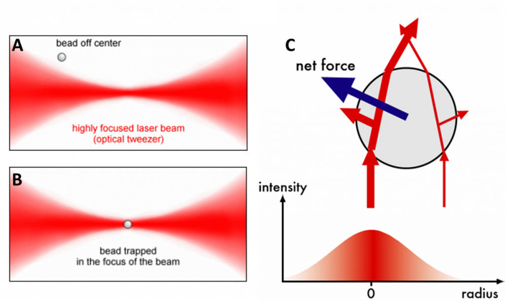
In OT, a laser beam is directed at a particle, cell or other microscopic objects. This object will scatter the laser beam in different directions (depending on the object’s shape, as seen in Fig.1C), changing the momentum of the light which results in a force exerted on the object (Newton’s third law of motion). The object moves towards the point where the beam is most focused and is trapped there. This concept is outlined in Fig.1. By using multiple beams and moving their focus points, the object can be moved around in three dimensions with incredible precision.
Because OT lasers are in the infrared part of the spectrum, they don’t interfere with normal fluorescence techniques (which use visible light) and the two techniques can be used in combination to great effect. OT can also be used on samples that are smaller than the wavelength of light (~200 nm), the main change being that the way the light is scattered is very different: Mie scattering for larger than 200 nm, Rayleigh scattering for smaller than 200 nm. Lastly, the force of the laser can be altered by adjusting the power, spread and polarisation.
This precision can be exploited by attaching biological molecules or tissues to spherical probes, which are then controlled with the OT to measure forces or pin objects in place. Many factors affect the applied force such as the power, spread, and polarization of the beam, and the size, structure and refractive index of the target.
When trapping biological objects such as cells directly, particles are seldom spherical and contain variations in refractive index that remove the possibility of exact analytical models of the response of the particle to the beam. However, such particles can still be trapped and approximate models can be formulated (Favre-Bulle et al. 2017).
Uses Of Optical Trapping
When targeting objects of well-defined shape and optical properties, the force exerted upon the object can be very precisely calculated, meaning not only can this technique be used to move and trap targets, but also to measure the mechanical properties of surfaces such as cell membranes.
Alternative techniques to measure mechanical properties of membranes, such as Atomic Force Microscopy (AFM), are common. However, AFM relies upon physical contact between a probe on a stiff cantilever and the substance of interest, which can easily damage the soft tissues found in biological samples. Measuring force through a probe in an optical trap, however, can be exceedingly gentle in comparison, with the force adjustable through changing laser power.
Another powerful companion technique for optical trapping is single-molecule fluorescence microscopy, whereby the fluorescent response from single molecules is detected. Fluorescent yields for single molecules are typically very low, so the trapping of cells in a known position without the need to bind the cell to a surface can allow for clearer imaging. Combining the two techniques can provide information about the presence, identity, spatial dynamics, and conformational dynamics of single biomolecules, alongside observation and control with ~nm spatial resolution, ~ms temporal resolution and ~pN-scale applied forces (Hashemi Shabestari et al. 2017).
Further, optical trapping can be used to hold biological samples in place for super-resolution imaging techniques such as PALM/STORM, which require long image sequences to build a composite image of sub-diffraction-limited structures. Optical trapping can take the place of biologically invasive adherence of cells to glass, or cell fixing (Diekmann et al. 2016).
Systems
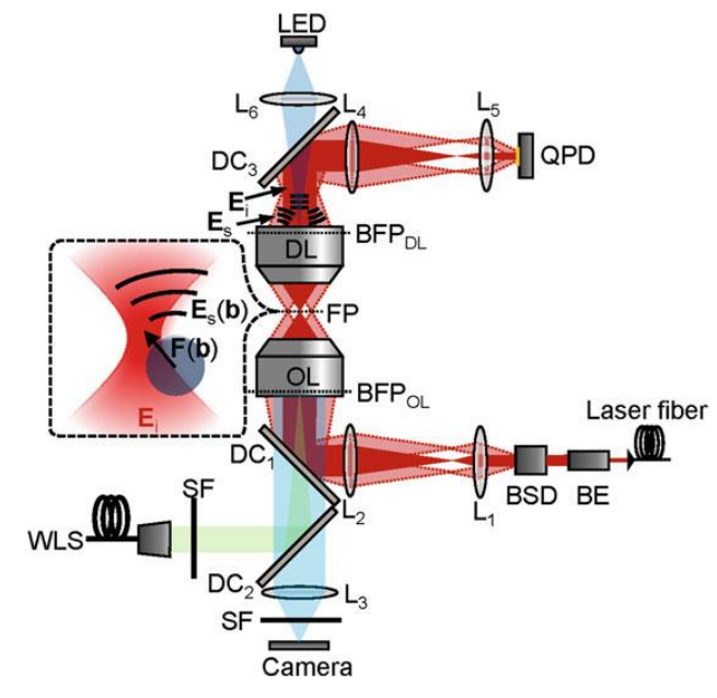
An optical trapping system is typically built on top of a commercial brightfield or fluorescence microscope. A near-infrared (NIR) laser of typically 1068 nm wavelength is most commonly used (Hendricks & Goldman 2017, p78), to avoid absorption of light by water, and damage to biological tissues. An example can be seen in Fig.2.
Multiple trap systems can be produced from a single beam using beam splitters, via spatial light modulators (SLM), acousto- and electro-optic deflectors, scan mirrors or combinations of these devices, allowing simultaneous control of multiple trapped objects. SLMs even allow the transference of angular momentum to trapped objects, applying torque.
The light from the trapping laser is detected by either a quadrant photodetector (QPD) or specialist NIR camera, for alignment and analysis.
Applications
The ability to hold single cells in a fixed position and/or apply a well-defined force opened new doors for biological microscopy. It was first utilized to study E. coli flagella to measure the torque they produced (Block, Blair, and Berg 1989), and single kinesin motors, measuring the speed and binding forces of the kinesin attached to microtubules.
For modern in vivo studies of single cells, the ability to trap the cell in a known position without adherence to a surface is hugely beneficial for studying the natural behaviors and structures of the cell, and for allowing continuous observation over long timescales.
In recent years, optical traps are used increasingly in vivo to move biological objects up to a few microns in size, such as red blood cells (Zhong et al. 2013), erythrocytes, macrophages (Johansen et al. 2016) and injected nanoparticles. A recent study also demonstrated the ability of optical trapping to move large biological objects in vivo. Favre-Bulle and colleagues (Favre-Bulle et al. 2017) were seeking to characterize neural circuits related to the zebrafish vestibular system (for detection of movement). In larval zebrafish, the developing vestibular system consists solely of the force-sensing otolith or ‘ear stone’, the movement of which indicates to the zebrafish that it is experiencing a force. Conventionally, to stimulate the vestibular system, an organism would have to be physically moved. As most imaging methods rely on immobile specimens, this would rule out simultaneous stimulation and imaging. Using an optical trap, the researchers were able to move the 55 μm-diameter, roughly spherical otolith non-invasively and with precision, through the body of the zebrafish. The researchers were then able to simultaneously image the zebrafish’s brain and behavior.
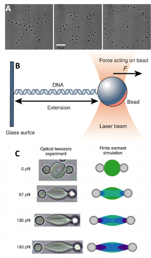
OT can be used very reliably when the object to be trapped is a regular and well-defined shape, like a perfect sphere. In reality, microscope samples have very irregular and complex shapes, like a DNA double helix, a cell or bacteria. This issue is bypassed by simply attaching a spherical probe (like a microbead) to the sample, and then moving the probe around with the sample attached. This allows for precise control over small complex structures such as DNA and bacteria (as seen in Fig.2B). However, particles that have strange shapes or variations in their refractive index can still be trapped (Favre‑Bulle et al. 2017).
As well as trapping or moving objects, OT reveals information about the mechanical properties of the object due to the forces exerted on it by the laser light. This allows for defined study into the biomechanics of complex yet regular shapes such as cell membrane surfaces. Optically exerting pressure means the technique is very gentle, especially when compared to alternatives such as atomic force microscopy (AFM) that can damage these samples. Some applications of OT can be seen in Fig.2.
OT pairs well with fluorescence microscopy techniques, especially single molecule fluorescence microscopy (SMFM) (see our single molecule application note). SMFM often features low levels of signal, meaning that trapping cells in a known position allows for a more reliable signal and clearer images. Combinations of OT with SMFM are popular as the two techniques together can provide information about the presence, identity, spatial/conformational dynamics and biophysical behaviors of particles while featuring nanometre spatial resolution, millisecond temporal resolution and piconewton applied forces (Hashemi Shabestari et al. 2017).
OT also pairs well with super-resolution localization techniques such as PALM and STORM (see our super-resolution learn page for more), which need to take thousands of frames of samples in order to build a super-resolution image. By holding samples in place with optical tweezers (and rotating their position if needed) the image quality is further improved, and harsh techniques such as cell fixing or adhering cells to glass can be avoided (Diekmann et al. 2016). Diekmann and colleagues demonstrated that holographic optical trapping can be used to immobilize rod-shaped bacterial cells, for the first time allowing dSTORM imaging of a bacterial cell-free in space. Further, the position and orientation of individual cells can be directly controlled, opening the door for deeper insights into the nanoscale structures of biological samples.
Cameras For Optical Trapping
The use of optical trapping does not itself influence the camera requirements of a microscopy technique, as trapping systems can be used alongside a huge variety of microscopy techniques, including brightfield, epi-fluorescence, spinning disk and laser scanning confocal, STED, single-molecule fluorescence, and PALM/STORM super-resolution techniques.
For brightfield applications, a camera with a large field of view and smaller pixels to improve resolution may give the best results. For more demanding applications such as super-resolution imaging (PALM/STORM and companion techniques), a more sensitive camera with high QE and low noise, capable of high speeds, would be recommended.
Summary
In general, OT is remarkably useful for the ability to trap cells in a known position without surface adherence, as it allows for continuous observation and study of natural cell structures and behaviors over the long term, with the only effect on the cell being the negligible force exerted by OT lasers. OT is not just limited to cells or smaller structures like DNA, larger biological objects can also be trapped and moved.
Download As PDF
References
Ashkin, A., J. M. Dziedzic, J. E. Bjorkholm & Steven Chu. (1986) Observation of a Single-Beam Gradient Force Optical Trap for Dielectric Particles. Optics Letters 11(5): 288. https://www.osapublishing.org/abstract.cfm?URI=ol-11-5-288.
Block, Steven M, David F Blair & Howard C Berg. (1989) Compliance of Bacterial Flagella Measured with Optical Tweezers. Nature 338(6215): 514–18.
Curtis et al (2002), Dynamic Holographic Optical Tweezers, University of Chicago https://physics.nyu.edu/grierlab/dynamic4c/
Diekmann, Robin et al. (2016) Nanoscopy of Bacterial Cells Immobilized by Holographic Optical Tweezers. Nature Communications 7.
Favre-Bulle, Itia A., Alexander B. Stilgoe, Halina Rubinsztein-Dunlop & Ethan K. Scott. (2017) Optical Trapping of Otoliths Drives Vestibular Behaviours in Larval Zebrafish. Nature Communications 8(1). http://dx.doi.org/10.1038/s41467-017- 00713-2.
Hashemi Shabestari, M. et al. (2017) 582 Methods in Enzymology Recent Advances in Biological Single-Molecule Applications of Optical Tweezers and Fluorescence Microscopy. 1st ed. Elsevier Inc. http://dx.doi.org/10.1016/bs.mie.2016.09.047.
Koch, M. D., & Shaevitz, J. W. (2017). Introduction to Optical Tweezers. Methods in molecular biology (Clifton, N.J.), 1486, 3–24. https://doi.org/10.1007/978-1-4939-6421-5_1
Johansen, Patrick Lie et al. (2016) Optical Micromanipulation of Nanoparticles and Cells inside Living Zebrafish. Nature communications 7: 10974.
Wu C. et al. (2018) Manipulation of Biological Cells Using a Robot-Aided Optical Tweezers System, Micromachines 9, 245
Zhong, Min-Cheng et al. (2013) Trapping Red Blood Cells in Living Animals Using Optical Tweezers. Nature communications 4: 1768.