
Introduction
There are two significant challenges in biological imaging that conventional fluorescence microscopy cannot overcome. Firstly, biological specimens are 3D structures and in order to fully understand them, we often need to construct 3D images. Secondly, many processes that biologists wish to study occur inside biological structures but other cell features such as the cell membrane block a clear view.
These problems are difficult to overcome due to the need to pass light through the entire sample to illuminate the chosen image plane. This gives little control over where the returning light will be coming from. Light from out of focus planes or bright features above and below the desired plane cannot be blocked with conventional fluorescence microscopy.
Confocal microscopy offers the solution to this issue. Confocal microscopy uses optical sectioning to take multiple, thin, 2D slices of a sample to construct a 3D model from them. This process removes the out-of-focus light from other planes. The first design of a confocal microscope was the laser scanning confocal microscope (LSCM), but this was soon followed up by the spinning disk confocal microscope (SDCM), as detailed in the sections below.
Laser Scanning Confocal Microscopy
LSCM features a laser light source, where the beam passes through a pinhole in the excitation light path, while the emission light from the illuminated point on the sample passes through another pinhole to a detector, as seen in Fig.1.
To generate an image, the excitation laser is raster-scanned across the sample in X and Y, then an image is reconstructed from the detected light. A moveable Z-stage is required for imaging in the Z direction and generation of 3D images. This technique generates high-quality images but only at a rate of 1 second per image, a very slow imaging speed. Additionally, LSCM is limited to low-efficiency photomultiplier tubes as detectors and the considerable photobleaching/photodamage to live samples due to the use of a slow-moving and highly concentrated laser. Another technique was therefore needed for live cell work, or for the imaging of fast processes.
Spinning Disk Confocal Microscopy
SDCM solved the issues of LSCM problem by using multiple pinholes to scan the entire image, parallelizing the process and greatly increasing the speed of acquisition. Compared to LSCM, SDCM is high-speed, high-sensitivity and simple to implement. This makes it a good choice for studying 3D structures, fast dynamic processes, long-term time-lapse or details inside the cell membrane, all possible with live cells. The most advanced design of spinning disk unit was engineered by Yokogawa Electric Corporation of Japan and it remains the ‘gold standard’ for microscope manufacturers today.
Yokogawa Spinning Disk
The Yokogawa spinning disk unit consists of two coaxially aligned disks: a collector disk and a pinhole disk, with a dichroic mirror positioned between them. Each disk contains pinholes arranged in a series of nested spirals. The pinholes on the collector disk contain Fresnel microlenses that focus light onto the pinhole disk, as the two disks are co-aligned. The pinholes are at the focal plane of the microlenses, as seen in Fig.2.
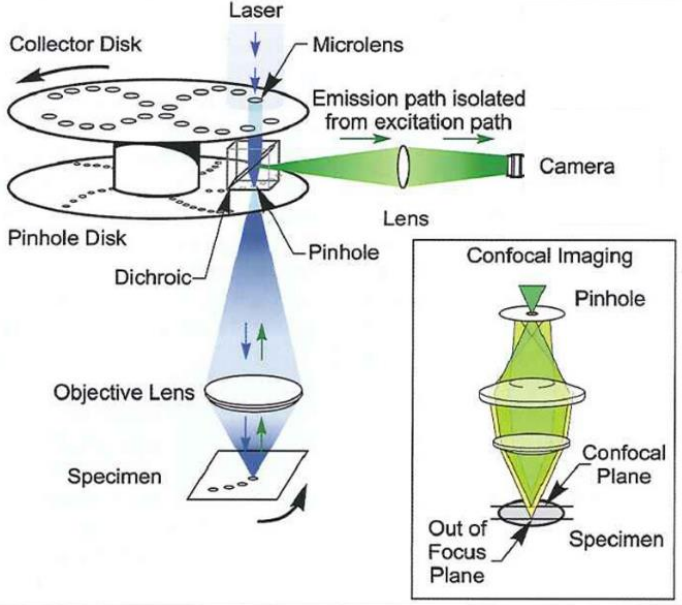
Laser excitation is introduced from above and projected onto the collector disk through a collimating lens. The light passes through the microlenses and the dichroic mirror and onto an area of pinholes on the pinhole disk. When the disks are spun, the pinholes scan across entire image rows in sequence. These pinholes are positioned so that every part of the image is scanned with every 30° rotation of the disks. The rotation speed of the disk, therefore, determines the maximum image acquisition speed.
Fluorescence emission from the sample is collected by the objective lens and focused back onto the pinhole disk. The pinhole blocks out-of-focus light from passing through the disk so illumination light from one pinhole creates emission light that is gathered by the same pinhole. This light is reflected by the dichroic mirror and passes through an emission filter before being focused onto the camera sensor for detection.
Spinning disk microscopy is essentially a light rejection technique, so a high photon budget is necessary for high-quality imaging. For this reason, the Yokogawa spinning disk unit uses beam shaping, collimating lenses and microlenses to substantially increase the amount of light throughput to increase photon collection efficiency. Furthermore, the pinhole pattern ensures that image frames are homogenously illuminated so there is no light intensity gradients across the field of view and no scanning stripes.
Types Of Yokogawa Spinning Disk
There are currently two main types of Yokogawa spinning disk units: the CSU-X1 and the CSU-W1. The mode of operation is the same but there are important differences between the two:
- CSU-X1: the faster unit, with scanning speeds of up to 10,000 rpm (theoretical maximum acquisition speed 2000 fps)
- CSU-W1: slower scanning speed of up to 4000 rpm (theoretical maximum acquisition speed 200 fps) but the field of view is almost 4 times larger in order to better accommodate larger field of view camera sensors such as new state of the art CMOS devices. It also features decreased crosstalk and an extended near-infrared spectral range, allowing for sharper images of regions deeper inside live cells.
Historically, there were two other unit models, the CSU-10 and the CSU-22, which differed by having rotational speeds of 1800 rpm (max 260 fps) and 5000 rpm (max 1000 fps), respectively. These unit models are no longer being produced but there remains a significant amount of them still in active use.
When performing fast imaging with Yokogawa spinning disk units, the disk rotation speed must be adjusted to match camera exposure time. Each area of the image is scanned by the pinhole disk every 30° rotation of the disk, therefore the exposure time of the camera must be an integral multiple of the time necessary to perform one 30° rotation. If exposure times are not matched to the scan speed, striped patterns can become superimposed on the image. This is not so important when using long exposure times (~100 ms) but will become a problem if it is necessary to image at 200 fps (5 ms exposure) and above.
A second camera port is commonly used with Yokogawa spinning disk units to allow simultaneous two-color imaging or, historically, to have an EMCCD on one port for low-signal imaging and a CMOS camera on the other port for a larger field of view and higher speed imaging. However, with the advent of high sensitivity, back-illuminated sCMOS devices, these two functions can now be performed with one camera.
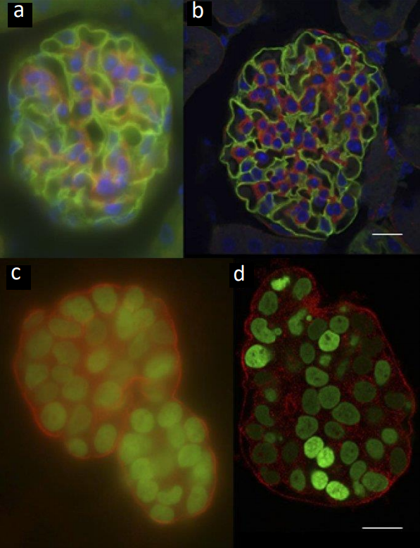
An example of imaging with widefield technologies vs confocal technologies can be seen in Fig.3.
Cameras For Yokogawa Spinning Disk
Any camera can be used with a Yokogawa spinning disk unit but the best performance can be achieved with a sensitive camera with high speed and a large field of view
Modern sCMOS cameras have been used for SDCM due to their large field of view, high speed and varied pixel sizes to maximize resolution – a pixel size of 6.5 um will ensure Nyquist sampling with 60x magnification and a pixel size of 11 um will ensure Nyquist sampling with 100x magnification.
Back-illuminated sCMOS cameras also feature equivalent sensitivity to EMCCD camera with the field of view, speed and pixel size advantages of sCMOS technology. This allows the sensitivity to be maximized without having to trade-off speed or field of view, ensuring faster, more physiologically relevant data acquisition.
Summary
The Yokogawa spinning disk system is a major component in spinning disk confocal microscopy, allowing for high speed, multi-channel imaging with low phototoxicity, improving on previous laser scanning confocal technology. Pairing such a system with a powerful and sensitive sCMOS camera allows for fast, flexible imaging of live cells and other samples.
References
Jonkman, J. and Brown, C. M. (2015) Any Way You Slice It – A Comparison of Confocal Microscopy Techniques. Journal of Biomolecular Techniques 26: 54-65
Nelson, M., Ledoux, J., Taylor, M., Bonev, A., Hannah, R., Solodushko, V., Shui, B., Tallini, Y., & Kotlikoff, M. (2010) Spinning Disk Confocal Microscopy of Calcium Signalling in Blood Vessel Walls. Microsc Anal (Am Ed). Mar 1; 24(2): 5– 8.
https://www.yokogawa.com/eu/