
Introduction
Once you have acquired a splitter, the next step is to set up the hardware and software for your microscope or imaging system. This technical note covers the hardware portion of set up, namely how to physically align the splitter with your imaging hardware.
This setup is different depending on whether the splitter is a multi-camera adapter that allows multiple cameras to view the same sample; or an image emission splitter that splits the image of a sample into multiple images across the sensor of a single camera.
Multi-Camera Adapters
The TwinCam and MultiCam splitters are compatible with most scientific C-mount and F‑mount cameras, and allow the use of multiple cameras from a single microscope port. Bold text refers to locations on the splitter that are labeled on the diagrams towards the end of this article.
Mounting To Your Microscope
- Connect the splitter to your existing 1x camera C-mount (or confocal unit if appropriate).
- If using an inverted microscope, support jacks are normally supplied to support the weight of the splitter. Position the support jacks in the jacking point on each output. The height can be adjusted and locked in position with the blue locking collar. The TwinCam has an included spirit level to aid setup.
- Remove the C-mount camera tube and protective dust cap. The clamping screw may need to be loosened (using provided 2.5 mm hex key).
- Screw each camera onto a C-mount camera tube and replace it on each arm of the splitter with the calibration ring still in place.
Aligning Two Images
- (For the MultiCam, first identify the transmitted port (1) from the diagram). View a live image on the transmitted port. For the initial setup, it is essential to be able to view all four edges of the rectangular aperture, therefore it is not advisable to use a fluorescent sample at this stage.
- Close the rectangular aperture until in view on the image and rotate the camera until square, then lock off the clamping screw.
- Insert the calibration cube(s) (containing a 50% mirror) into the unit by removing the magnetic door cover. Magnets will ensure the cube locates correctly.
- Repeat steps 1 to 3 on the reflected port (TwinCam) or remaining ports (MultiCam).
- If the sample focus of the reflected camera is not precisely matching the focus of the transmitted camera, an adjustment is provided (to allow for any slight differences between the positioning of the camera sensor). Remove the calibration ring on the reflected port and move the camera in Z until focused. Lock-off the clamping screw once again.
- Images can now be overlaid in your imaging software and pixel aligned using two sets of XY controls.
- With the rectangular aperture still in view, center the transmitted port (1) by adjusting the transmitted H&V controls. It’s useful to use a central square or central crosshair as a reference point in your imaging software (if available).
- For TwinCam, center the reflected port using the reflected H&V controls.
- For MultiCam, an additional method of XY alignment on the three combiner cubes is necessary for fine adjustment of each of the remaining images
- Identify port (2) and combiner cube (1)
- With the rectangular aperture still in view, center the image on port (2) (using provided 1.5 mm hex key) by adjusting the H&V controls on combiner cube (1)
- Similarly, center the camera on port (3) with the H&V controls on combiner cube (2)
- Finally, center port (4) with the H&V controls on combiner cube (3)
- Note the all reflected images will be mirrored and will need to be flipped in your imaging software if overlaid
- Replace the calibration cube(s) with a filter cube for dual/multi-channel imaging.
- Open the rectangular aperture to slightly larger than the camera field of view to minimize scattered light.
For information on filter cube assembly and auxiliary component mounts, refer to the articles on Cairn Research’s website. Diagrams of the TwinCam and MultiCam can be seen in Fig.1 and Fig.2.
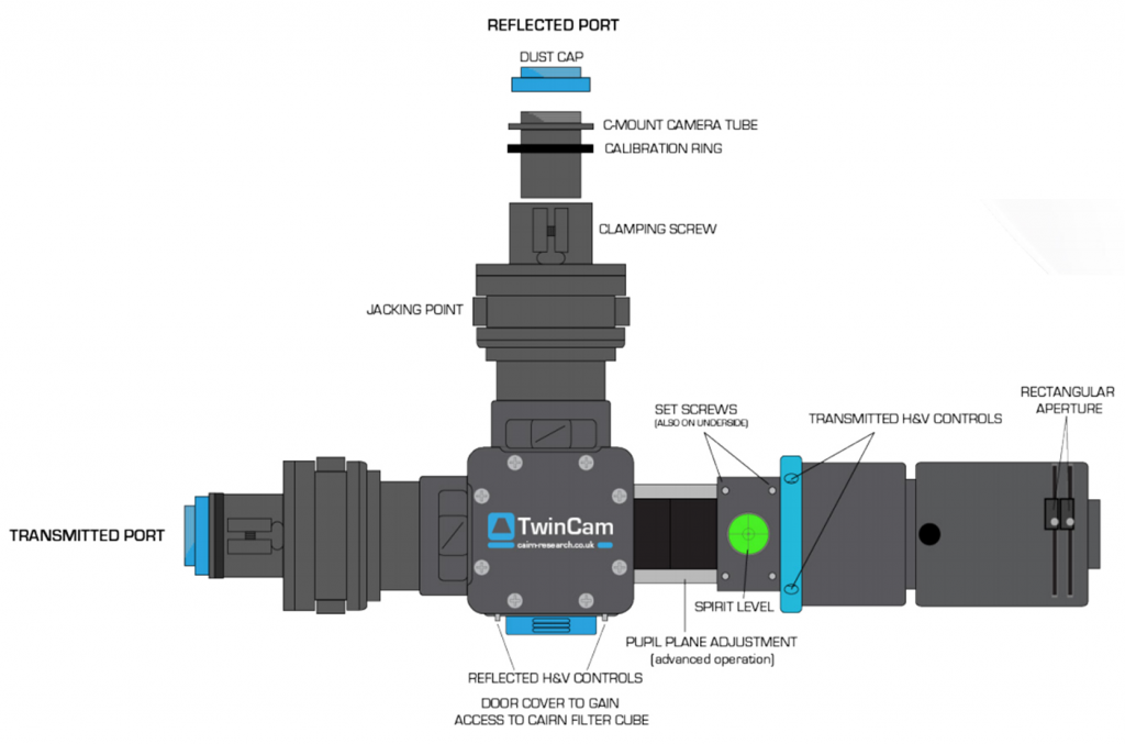
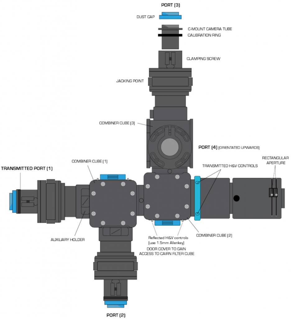
Image Emission Splitters
The OptoSplit II, OptoSplit III and MultiSplit V2 image splitters are compatible with most scientific C‑mount cameras. Before using these image splitters, it is important to first install the appropriate set of filters and mirrors for your application.
Installing the Splitter in the Light Path
- Before installing the splitter, first set up the microscope, camera, and software to give a clear image of an object of less than half the size of the camera frame. Ideally, this should be a real sample with appropriate optical properties for the installed filter set. Failing this a standard brightfield image can be used, but this can lead to arbitrary intensity differences between the split images.
- Once a clear image can be seen with the camera, switch the camera off and remove it.
- Fit the image splitter onto the microscope with the diaphragm oriented towards the output of the microscope.
- Fit the camera onto the output port of the splitter with the top of the camera oriented to lie parallel with the top of the splitter (to avoid image slant), regardless of horizontal or vertical orientation.
- A 1 mm nylon space is included with each splitter and may be required on the camera output mount if other hardware is installed (such as a shutter)
- Adjust the camera image to see a sharp picture of the aperture edge with a sample in focus. The image should line up with the edges of the aperture and should not have any rotation or slant in either direction. If your software can display a rectangular ROI then the image of the aperture can be aligned to this.
Operation Of Image Emission Splitters
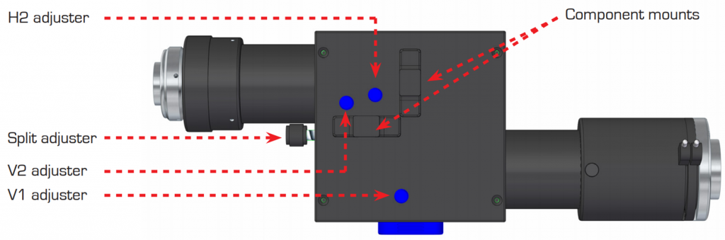
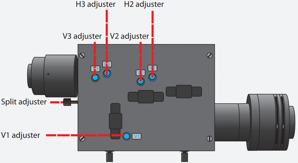
With the camera mounted, the split adjuster and aperture controls are the only controls that should be frequency adjusted. The remaining controls should remain untouched unless the filter becomes misaligned. For setup, it may be easier to use the calibration cube so that all channels display the same information. The bold text refers to points on the diagrams pictured in Figs.3, 4 and 5. The action of the split, H and V controls can differ between splitter types.
- Image splitters use a single control for adjusting image separation (split adjuster) and allows for different sized samples or camera chips to be used. There are additional controls for refining the ROI and centering the image, as shown in the diagram.
- V/H for vertical/horizontal adjustment, split for separation of images horizontally, trim to correct vignette (if one image appears darker towards one edge).
- To begin, set a conveniently sized aperture so the edges of the aperture are just visible within the field of view vertically and set horizontally depending on how many split images will be displayed. For example, the OptoSplit III should restrict the field of view to just under 33% of the horizontal.
- Image splitters are supplied with an adjustable rectangular aperture that allows the user to determine the ROI both vertically and horizontally. Once ROI has been adjusted, the aperture can be locked in place.
- Turn the split adjuster anti-clockwise to separate images along the horizontal axis. The reflected channel will be the rightmost image.
- Should the images be at different vertical heights, adjust the images using the V adjusters. V1 control will move the reflected channel (rightmost), V2 for the transmitted channel (for OptoSplit II), center image (for OptoSplit III) or top left (for MultiSplit V2), and then V3/4 for remaining images.
- Adjust the reflected channel into position first, as for some splitters (OptoSplit III) this image has no independent horizontal controls.
- Should the images have different horizontal separations, adjust the images using the H adjusters, which are again numbered for sequentially split images.
- When carrying out experiments the aperture should be set to mask the region of interest tightly so that the images are located as closely as possible on the camera chip. When the images are side by side on the camera chip, you are ready to image.
- (Troubleshooting) If one image appears darker towards one edge (vignetting), adjust with the trim control. Loosen the clamp screw on the underside of the image splitter by a quarter of a turn to free the trim control slider. Simply adjust until the vignette is eliminated. Once both images are the same intensity, re-tighten the clamp screen once more.
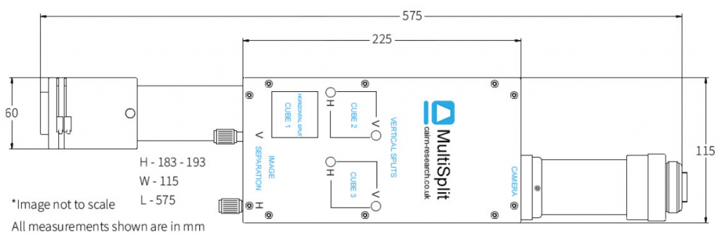
The split, horizontal (H) and vertical (V) controls can differ in action between the OptoSplit II, OptoSplit III and MultiSplit V2.
Summary
Once you have acquired a splitter, there are stages of hardware and software setup. This article detailed the hardware setup for multi-camera adapters TwinCam and MultiCam, as well as emission image splitters OptoSplit II, OptoSplit III, MultiSplit V2.