
Introduction
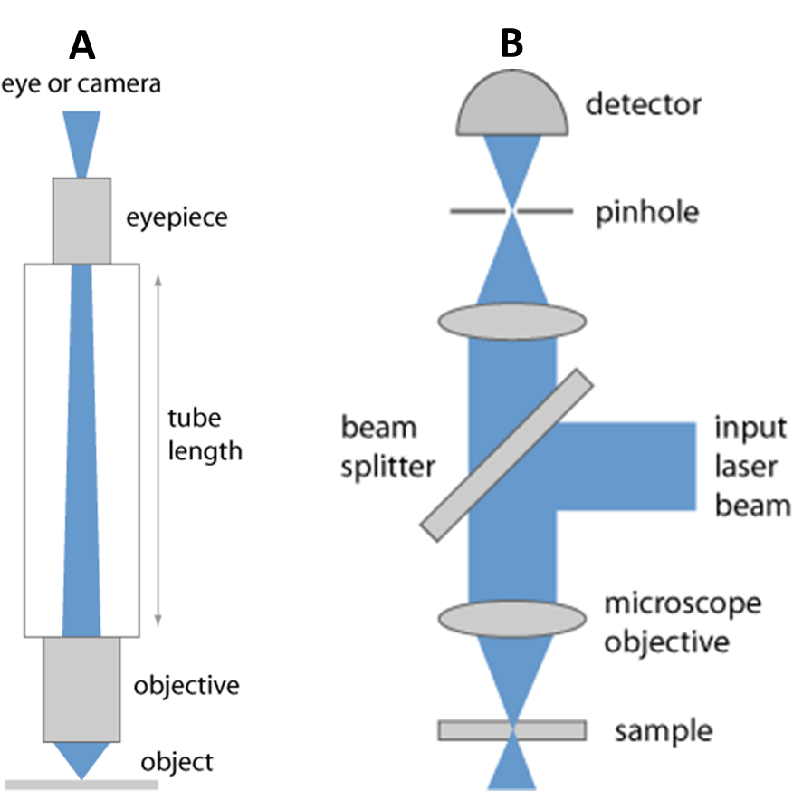
Early microscopes were essentially a tube through which light travels (Figure 1A), from a sample to the eye (or a camera), through some lenses. Modern microscopes have a variety of objectives, mirrors, and pinholes in order to obtain the best image (Figure 1B). The component of interest here is the beam splitter.
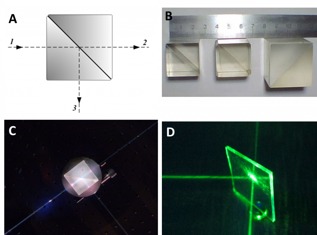
A beam splitter is an optical device that splits beams (such as laser beams) into two (or more) beams. Beam splitters typically come in the form of a reflective device that can split beams into exactly 50/50, half of the beam being transmitted through the splitter and half being reflected. Fig.2 outlines the uses of beam splitters.
Common types of beam splitter are either cube beam splitters or plate beam splitters (such as mirrors), as described below.
Cube beam splitters are made from two triangular glass prisms glued together, as seen in Fig.2A-C. The thickness of the glue is carefully adjusted so that, for certain wavelengths of light, half the light that enters the cube is reflected 90° and the other half is transmitted through the cube in the same direction as it entered, as seen in Fig.2A.
Half-silvered mirrors are a sheet of glass or plastic with a very thin coating of reflective metal, usually aluminum. The thickness of the metal coating allows for half the light to be transmitted, and the other half to be reflected at 90°. An example of this mirror can be seen in Fig.1D.
Dichroic mirrors are similar to metallic-coated mirrors but instead use a dichroic optical coating. Dichroic materials cause light to be split into distinct beams of different wavelengths (from the Greek dikhroos, meaning two-colored), depending on the material used the ratio of reflection/transmission can be changed.
Dichroic mirrored prisms are prisms that use a dichroic optical coating and can split beams up to three times. These devices could also be used in reverse, as a beam combiner.
When comparing plate/mirror and cube beam splitters, the mirror splitters can tolerate more powerful beams of light, but the cubes have far better durability and are easier to handle. While both mirror and cube beam splitters can be used for simple light beams, they can also split beams carrying an image, which makes beam splitters a powerful tool for microscopy.
Splitter Applications
Two major examples of the usefulness of beam splitters are:
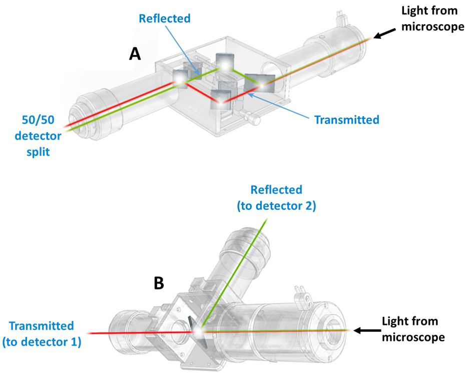
Emission image splitters: splitting image light from a microscope and re-aligning it so one camera can detect multiple images (Fig.3A)
Multiple camera adapter: splitting image light from a microscope into multiple cameras so that each one handles a specific wavelength (Fig.3B)
Emission Image Splitter
Emission image splitters allow for a single camera to image at multiple wavelengths by splitting the camera sensor into sections and projecting emitted light onto each part of the sensor. The optics within an emission image splitter can be seen in Fig.4.

These splitters act as an interface between the microscope and the camera, emitted light from the sample passes from the microscope to the splitter, and are split based on wavelength before being projected onto sections of the camera sensor. Splitters can split images two, three or even four times based on wavelengths, allowing researchers to image multiple fluorophores simultaneously rather than having to switch channels manually or electronically. Examples of emission image splitters can be seen in Fig.5.
These splitters all attach to standard C-mount ports on microscopes and offer standard output ports for cameras. This makes these splitters a seamless interface, allowing for multiple images on a single camera.
Emission image splitters have a wide variety of uses, as they can split an image across a camera sensor based solely on wavelength, polarization or amplitude. The main advantage is the simultaneous imaging at multiple wavelengths. If researchers want to image two different fluorophores, typical imaging systems involve manually or electronically cycling through filters in order to image at the desired wavelength. With a splitter, both wavelengths are imaged simultaneously, suitable for long term experimentation, fast dynamic events and any imaging setup that involves multiple fluorescent probes. Brightfield and fluorescence can be imaged simultaneously if desired, and splitting based on polarization allows for flexible experimental setups. Advanced microscopy techniques such as voltage/calcium imaging, Förster Resonance Energy Transfer (FRET), spinning disk confocal and Total Internal Reflection Fluorescence (TIRF) could all benefit from an emission image splitter.

While an emission image splitter can greatly enhance any imaging system by allowing for simultaneous imaging at 2/3/4 different wavelengths, the main disadvantage is that each channel occupies space on the camera sensor. When using a two-way splitter, the camera sensor is cut in half in order to resolve two images simultaneously. The two images have half the resolution and field of view due to only having access to half a sensor each. With large camera sensors, this isn’t such an issue, but if a four-way splitter is used on a smaller camera sensor, images may not be resolved properly due to only having a small portion of the sensor to interact with.
Multiple Camera Adapter
While an emission image splitter allows for multiple images on a single camera, the multiple camera adapter does the opposite: allows multiple cameras to image the same sample. As seen in Fig.3B, a single splitter sends half the light (reflected) from the microscope to one camera, and the other half (transmitted) to a second camera, split based on wavelength, polarization or amplitude. This setup allows for multiple cameras on one microscope port.
Different multiple camera adapters allow for increasing numbers of cameras on the same port, with up to four cameras imaging the same sample. These devices can be seen in Fig.6.

These splitters work as an interface between the microscope and the cameras, opening up a single microscope port for use with as many cameras as desired. While using an emission image splitter involves decreasing the camera sensor size for each image in order to acquire images simultaneously, there is no such trade-off with the multiple camera adapter, both cameras retain their full field of view and resolution but can each image the same sample at a different wavelength. This allows for the full potential of each camera to be utilized. In addition, if imaging at challenging wavelengths (such as ultraviolet (UV) or near-infrared (IR)), one camera can be used to cover these wavelengths, while still imaging at conventional fluorescence wavelengths with another camera.
The main drawback is the need to buy multiple cameras as well as a splitter, making the multiple camera adapter the more expensive option. Despite this additional cost, the significant increase in resolution and field of view make the multi-camera adapters an attractive option for simultaneous imaging.
Summary
In summary, if your experiments would benefit from simultaneously imaging your sample at different wavelengths, polarization states or amplitudes, splitters allow for more flexible experimentation. Whether this involves one image being split across one camera or one sample being split across multiple cameras, the numerous splitter devices available allow for more customizable research and better multi-channel imaging.
For more information about splitters, please refer to our other tech notes on this subject.