
Introduction
Once you have acquired a splitter, the next step is to set up the hardware and software for your microscope or imaging system. This technical note covers the software portion of set up, namely how to use a splitter with the open-source microscope control software µManager.
This setup is different depending on whether the splitter is a multi-camera adapter that allows multiple cameras to view the same sample; or an image emission splitter that splits the image of a sample into multiple images across the sensor of a single camera.
Multi-Camera Adapters
Using a filter to switch between fluorescent channels, manually or electronically, introduces delay and movement into the imaging process. Imaging multiple fluorescent channels simultaneously is a big advantage when studying fast dynamic biological processes. µManager can acquire different channels from separate, synchronized cameras through the Multi Camera virtual camera device, providing a larger field of view. To use this functionality, the cameras need to have the same number (rows and columns) of pixels and the same number of bytes per pixel (i.e. the size of the images in the computer’s memory needs to be identical). Multi-camera setup is as follows:
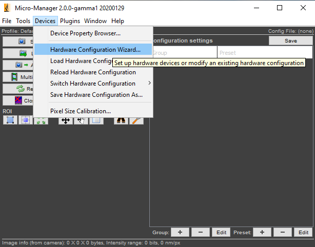
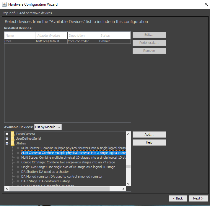
After installing two or more physical cameras to your imaging hardware (or two virtual “Demo Cameras” for testing), go to µManager’s Hardware Configuration Wizard (Fig.1) and add the Multi Camera virtual camera device from the “Utilities” device group to your current configuration. The Multi Camera virtual device’s purpose is to broadcast the commands it receives to multiple cameras and to pass any acquired images from its child cameras back to the application.
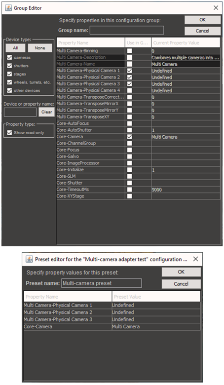
In the main µManager window, edit the System configuration group to add the Core‑Camera property and the Camera1/Camera2/Camera3 properties from the Multi Camera device. Then edit the System-Startup configuration preset, and set Core‑Camera to “Multi Camera” and the Camera properties to the appropriate physical cameras.
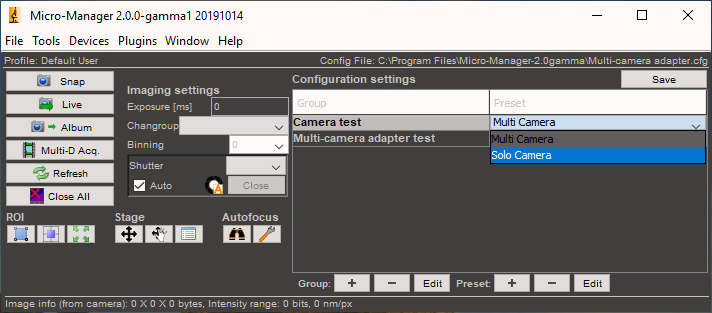
(Optional) It may be convenient to add an extra “Camera” configuration group, with the sole property “Core”-”Camera”. This will produce a drop-down menu on the main window that allows you to choose between imaging from either of the individual physical cameras or Multi Camera mode.
Exposure and binning settings will be propagated from Multi Camera to the physical cameras whenever they are set from the user interface. Focus on a sample with particles that can be imaged in two channels and turn on live mode to observe how the two cameras are overlaid as a pair of channels.
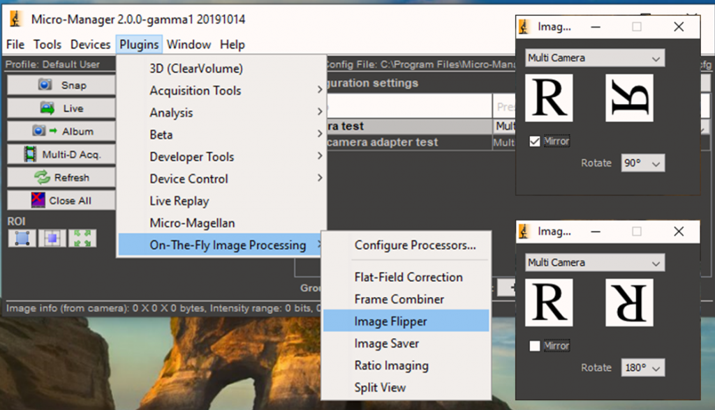
(Troubleshooting) If the image from one camera is mirrored or the camera cannot be rotated, use the “Image Flipper” Plugin to properly align the images. Once the orientation is correct, perform fine adjustments to the two cameras to get their images precisely registered.
In order to obtain multichannel images, open the Multi-Dimensional Acquisition window, and set up a two-channel acquisition (for example, Cy3 and Cy5). Create a 10-frame sequence with no time interval between frames, and press the “Acquire!” button. Multi-channel, multi‑camera acquisitions produce an image set with several synthetic channels. These synthetic channels will have names combining the name of the camera with the name of the physical channel, e.g.: “Camera1-Cy3”, “Camera2-Cy3”, “Camera1-Cy5”, “Camera2-Cy5”.

(Troubleshooting) To get perfect (sub-pixel) registration between the images on the two cameras, image registration software will almost invariably be necessary. One such option is the ImageJ plugin “GridAligner”, which uses a calibration image to automatically deduce the optimal affine transform function and applies the transform to other experimental images sets.
Image Emission Splitter
These splitters involve using mirrors or lenses to project multiple images side‑by‑side onto the same camera sensor. In this manner, a single camera can display two, three or even four separate wavelengths or fluorophore channels across its sensor.
After installing and aligning a camera and splitter to your imaging hardware, open µManager and use the Split View plugin in order to separate the split image into individual channels in software.
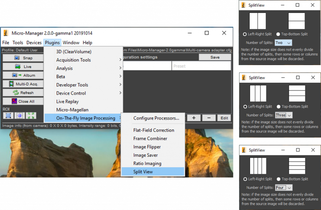
Split View takes a single image from your camera and cuts it along either vertical or horizontal lines, assembling multiple images from the cut result. Split View can do 2‑, 3-, 4-, or 5-image splits, and you can layer multiple Split View plugins to create both horizontal and vertical splits. You can set the color of each channel and use either a left-right or top-bottom split.
An alternative to Split View is the Cairn Image Splitter Analyzer, an Image J plugin that allows the analysis of split images. For users with many images, this plugin can batch process images in a folder. To use, install the Image J plugin and open the software with the split image already open in Image J.
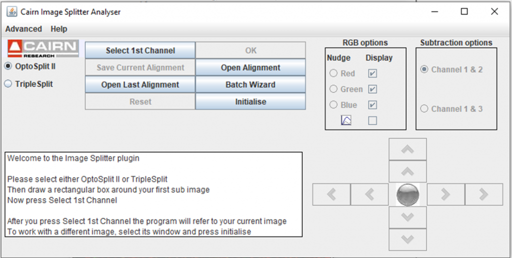
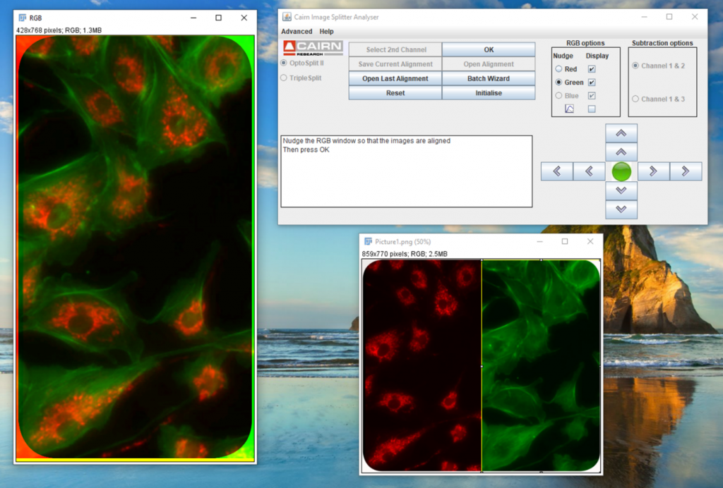
Draw an ROI box around the first channel of the image (red in the example on Fig.9) and press Select 1st Channel. Move the box to the second channel and press Select 2nd Channel. Repeat for the third channel if necessary. It is important that the ROI box does not change the size between selections.
Once all channels have been selected, a composite image will be generated. If the alignment of any channel is off, select the channel in RGB options and use the arrows to move the image until alignment is achieved.
Summary
Once you have acquired a splitter, there are stages of hardware and software setup. This article detailed the software setup for multi-camera adapters TwinCam and MultiCam, as well as emission image splitters OptoSplit II, OptoSplit III, MultiSplit V2, using both MicroManager and Cairn Image Splitter Analyzer.