
Introduction
Applications such as light-sheet microscopy and spinning disk confocal microscopy often utilize rolling shutter readout of CMOS sensors to enhance image quality. Programmable Scan Mode (PSM) allows additional control over the rolling shutter and readout, such as adding delays to groups of rows and changing the readout direction. PSM can be found on our Prime and Kinetix families of CMOS cameras.
PSM acts like a full-width region of interest that rolls across the columns of the sensor with the rolling shutter readout. Should the region of interest coincide with the focus of illumination light, as in certain types of light-sheet microscopy or line scan illumination, then out-of-focus or scattered light collection can be minimized.
Programmable Scan Mode
Rolling shutter readouts digitize pixel intensities one row at a time. A “reset” signal starts at the first row of the sensor and resets or clears the row of pixels of any collected signal, effectively starting the exposure. This reset signal sweeps downwards towards the last row, propagating at a rate defined as line time, which is the amount of time it takes to activate each row of pixels.
The reset signal is followed by a “readout” signal which causes the amount of light captured by each row of pixels to be digitized and readout of the sensor. The readout signal signifies the end of the exposure or light capture. The time between the reset and readout signals is defined as the exposure time, the amount of time each pixel is in the light collection phase.

The readout signal always follows the reset signal by a delay equal to the exposure time. This exposure time is always a multiple of the line-time of the sensor. If the exposure time is set to be equal to 10 line times, the readout signal is behind the reset signal by 10 rows.
With PSM, these factors can be altered. Both the timing and direction of the scan can be controlled, as detailed in the next sections.
Scan Timing
For timing, there are three main settings for PSM that can be altered in imaging software:
- Auto: The default option, the line time is set to one line, prevents user from setting a delay between reset and readout signals.
- Line Delay: Adds a delay after the line time, slowing the reset and readout signals, and increasing the effective line time.
- Scan Width: Allows the user to set the number of rows between the resert and readout signal, specifying the number of rows in the detection region.
Modifying and increasing the line-time of a sensor gives greater flexibility to control the number of rows between the reset and readout signals and the exposure time, allowing for both an optimized experimental setup and adequate signal levels. Controlling the line-time makes synchronization between the illumination and acquisition simpler, providing control over the rate at which the exposing rows propagate down the sensor, as shown in Fig.2.
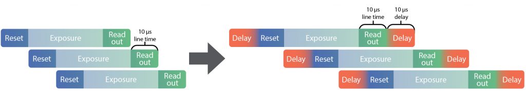
Line Delay
This delay is added onto the default line time, in increments equal to the line time:
Scan Line Time = Line TimeSensor + (Line TimeSensor × Scan Line Delay)
A value of 1 adds a delay equal to 1 line time. This results in an effective line time equal to double the value of line time.
Line TimeSensor = 10μs
Scan Line Delay = 1
Delay = 10μs × 1 = 10μs
Scan Line Time = 10μs + 10μs = 20μs
For cameras in the Kinetix family, there are modes that read two lines of the sensor at a time, which can complicate things when using PSM. This is most easily addressed by doubling the single-line read time specification and using the doubled value instead.
The frame rate when imaging in this mode is determined by the number of rows being imaged and the Effective Line-Time.
Readout TimeImage = Scan Line Time × NRows
Frame Rate = 1 ÷ (Readout TimeImage + Exposure Time)
The minimum line delay value is 1. This is also the default value when Line Delay mode is selected.
Scan Width
When in Scan Width mode the number of rows between the reset and readout signals will be calculated automatically.
Scan Width(Lines) = Exposure Time(Lines) ÷ Scan Line Delay
A Scan Width parameter is available and reports the number of rows between the reset and readout signals.
When PSM is set to Scan Width, the number of rows between the reset and readout signal can be set. It gives direct control to set the size of the imaging region.
Scan Width = Number of Rows between Reset and Readout
In the dual-line readout modes of Kinetix cameras, in cases where the input Scan Width is an even number of rows, the detection region contains an even number of rows. However, when the input Scan Width is an odd number of rows, the detection region contains one more row than the input. For example, a Scan Width value of 10 will have a detection region equal to 10 rows. In contrast, a Scan Width value of 11 will have a detection region equal to 12 rows.
When the Scan Width is set, the effective line-time required is automatically calculated.
Scan Line Delay = Exposure Time(Lines) ÷ Scan Width(Lines)
Scan Line Time = Line TimeSensor + (Line TimeSensor × Scan Line Delay
The Effective Line-Time is reported as the Scan Line-Time parameter in nanoseconds.
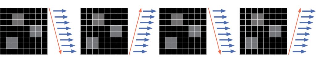
Scan Direction
For scan direction, there are also three options in imaging software:
- Down: The default option, the rolling shutter starts at the top row of the sensor and propogates down to the bottom row. Each new frame then starts again at the top row.
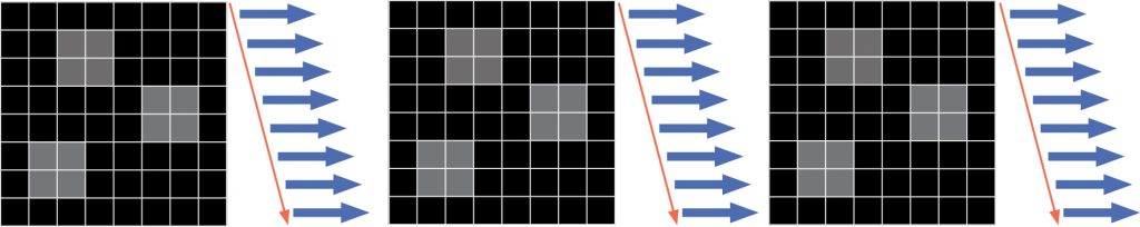
- Up: Inverts the direction of readout, which starts at the bottom and propogates up to the top row. Each new frame then starts at the bottom row. Images acquired in this mode are not inverted and are the same as with ‘Down’ mode.
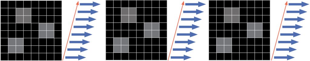
- Down-Up Alternate: With this mode the direction of readout alternates between frames. The rolling shutter first travels top to bottom, and for the next frame it travels bottom to top, and alternates between each frame. The image orientation when acquired in this mode will have no inverted frames and will be consistent with the Down scan direction.
Summary
Programmable Scan Mode is exclusive to Teledyne Photometrics scientific cameras and allows for unprecedented control over CMOS readout scanning, including timing, width, and direction. This mode can be used with certain applications such as light sheet/spinning disk, with strobing light sources, and/or where exposure time needs careful control, like with sensitive samples. Overall, Programmable Scan Mode can advance your imaging through camera control.