
Introduction
The spinning disk confocal microscope (SDCM) is a revolutionary tool for imaging in the life sciences, observing samples ranging from single molecules to live cells, featuring high speed, 3D and multichannel acquisitions. Many experiments and researchers use SDCM imaging systems for their imaging, and the technology has become well established.
SDCM allows for optical sectioning (imaging 2D planes from thick 3D samples) at high speed with considerably reduced photodamage or bleaching when compared to widefield. When paired with a highly sensitive camera, SDCM becomes a powerful technique for imaging in the life sciences. SDCM is primarily used for multichannel, high speed, high-resolution 3D imaging of live samples, potentially over the long term. Thicker samples can be used to allow for 3D imaging, such as zebrafish and brain tissues, but smaller, low-light samples can benefit from SDCM, such as neuronal circuits, actin cytoskeletons, and mitochondria.
This article will explore the past, present, and future applications for SDCMs, the capabilities of modern systems, and how SDCMs are likely to advance and evolve in the future.
Past
Early confocal microscopes used laser point scanning (LSCM), featuring a single pinhole and detectors such as photomultiplier tubes (PMTs) or avalanche photodiodes (APDs). These detectors featured a low quantum efficiency (QE), which is the rate at which photons of light are converted to electrons of charge in order to produce an image. With low QEs, information is lost due to light scattering or inefficient sensor designs. The QE of PMTs/APDs ranged from 20‑40%, meaning that these imaging systems operated at suboptimal efficiencies and limited the signal to noise ratio (SNR).
When SDCMs became available they offered higher speeds, less photobleaching, and scientific camera detectors. Due to the pinholes blocking illumination light, early SDCMs benefited from high-sensitivity cameras with large pixels such as EMCCDs. The electron-multiplying nature of EMCCDs resulted in negligible read noise and effective imaging at low light, especially compared to the alternative and older CCD technology, which was slower and less sensitive.
EMCCDs for Spinning Disk
Photometrics introduced the first scientific-grade EMCCD in 2000, the Cascade 650. Since then, the Photometrics Evolve series of EMCCDs were a great fit for early SDCMs, with pixel sizes up to 24×24 μm and QEs up to 95% thanks to back illumination. In terms of speed, the Evolve 128 delivered speeds up to 530 frames per second, matching up to spinning disk rotation speeds.
However, EMCCDs have several drawbacks:
- EMCCDs are expensive and therefore not easily accessible to all SDCM researchers
- EMCCDs feature EM Gain decay, these cameras have a limited lifespan and decay over time, requiring regular calibration in order for experiments to be quantitative or reproducible
- EMCCDs feature excess noise factor, due to the random nature of electron multiplication, photon shot noise is multiplied by a factor of 1.4x
- Due to small sensors, EMCCDs have a small field of view (FOV), up to 11 mm diagonal
- Due to the large pixels, EMCCDs have to be matched with high magnifications in order to achieve Nyquist sampling
- EMCCDs typically use a firewire interface, which is uncommon
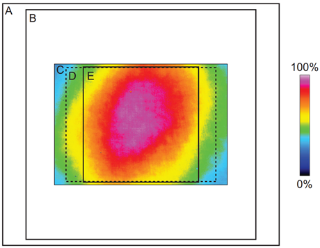
The limitations of EMCCDs also led to compromises in SDCM systems, which were designed to match typical CCDs/EMCCDs, featuring small FOVs and matching pinhole diameter/spacing and microlens focal length. Limited SDCM FOV can be seen in Fig.2, showing a CSU-X1 spinning disk system with a 12 mm diagonal FOV. Early SDCMs featured scanning speeds ranging from 1500-5000 rpm and could image up to a thousand fps, but slower detectors limited final acquisition speeds.
EMCCDs were an established technology and our Photometrics Evolve series paired well with SDCM imaging systems. However, imaging and camera sensor technology continued to evolve, bringing CMOS technology to the fore.
Present
The present day is over 20 years after the introduction of the first scientific-grade EMCCD, and over 50 years after the introduction of spinning disk confocal technology. During this time, SDCM technology has evolved in a number of different ways:
- The latest sCMOS camera sensors now feature back-illumination, up to 25 mm FOV, a range of pixel sizes for Nyquist at different magnifications, 95% QE and high acquisition speeds
- Larger FOV microscopes and SDCM systems allow for imaging up to 25 mm diagonal
- Super-resolution dual-disk SDCM systems available for imaging samples smaller than ~200 nm
- Disks can spin at up to 15,000 rpm, allowing for higher imaging speeds and capture of live dynamic samples
- SDCM systems can image with multiple sCMOS cameras in order to capture multiple wavelengths simultaneously
Scientific cameras have evolved alongside spinning disk technologies, allowing researchers to push past limitations in their imaging work.
Back-illuminated sCMOS vs EMCCD For Spinning Disk
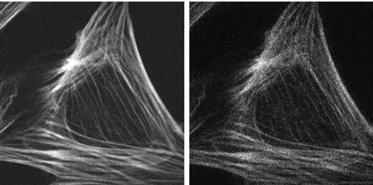
Once again Photometrics were trend-setters, introducing the world’s first back-illuminated sCMOS camera in 2016, the Prime 95B. With near-perfect 95% QE, an 11×11 μm pixel, and FOV up to 25 mm, the Prime 95B is an ideal modern camera for SDCM imaging. Fig.3 shows the difference between an image taken with an EMCCD and the Prime 95B on a SDCM system.

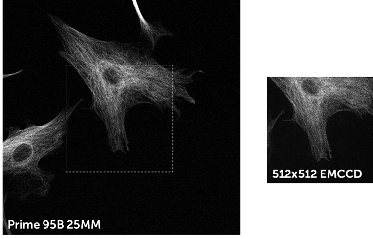
Thanks to a high QE, large pixel, and low read noise, the Prime 95B is a highly sensitive camera that can compete with EMCCDs in low light conditions. In addition, the Prime 95B has a much larger FOV, higher speeds, and higher resolving power than EMCCDs, while also being cheaper and avoiding the classic EMCCD downsides such as EM decay over time and excess noise factor (as seen in Fig.3 on the EMCCD image). The FOV difference between a 512×512 EMCCD and a 25 mm sCMOS can be more clearly seen in Fig.4, comparing the same sample in Fig.3 but over the full sensor. For more comparisons between an EMCCD and the Prime 95B on a spinning disk system, see our tech note.
Back-illuminated sCMOS vs Front-illuminated sCMOS For Spinning Disk
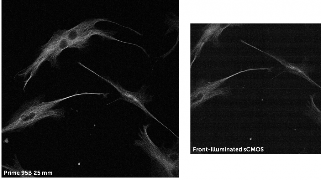
Front-illuminated sCMOS cameras feature a lower QE but can also use split sensors, this often results in artifacts and fixed pattern noise, all of which affect the acquired image at low light. The effect of a front-illuminated split sensor vs a back-illuminated Prime 95B single sensor can be seen in Fig.5.
The use of a modern back-illuminated sCMOS allows for the highest currently-available peak QE, a clean bias lacking patterns/artifacts, and huge improvements in the field of view (FOV) and acquisition speed over EMCCDs. Many modern SDCM systems have adopted back-illuminated sCMOS technology for the numerous benefits, allowing SDCM imaging to image fast dynamic live samples across a large field of view without sacrificing sensitivity and signal to noise ratio.
Super-Resolution Spinning Disk
As outlined in our article on super-resolution spinning disk confocal microscopy, there are spinning disk systems that can break the diffraction limit of light and image samples below ~200 nm, while retaining the high speed and 3D optical sectioning of SDCM.
Essentially, due to the dual pinhole setup of confocal microscopes, there are two point spread functions (PSFs) in a SDCM: the excitation PSF and the emission PSF. These two PSFs are offset, by narrowing and altering these PSFs the resolution of the system can theoretically improve by √2x, up to 2x after deconvolution.
This narrowing of PSFs could be done with far smaller pinholes, but this blocks too much light. Instead, optical photon reassignment is performed using another set of lenses on the underside of the pinhole disk, narrowing the PSF and reassigning photons to the most probable position they originated from, as seen in Fig.6.

These super-resolution SDCM systems can have a maximum resolution limit of ~120 nm (with standard SDCM it is around ~250 nm) and can image live samples at up to 200 fps (by rotating the disk at 4000 rpm) using most fluorescent dyes. This opens up many options for both researchers doing super-resolution imaging looking for more speed and better 3D imaging, as well as established SDCM researchers who are looking to resolve smaller samples.
The super-resolution (and single-molecule localization microscopy) techniques photoactivated localization microscopy (PALM) and stochastic optical reconstruction microscopy (STORM), are also compatible with SDCM. These techniques have also been shown to benefit from super-resolution processing algorithms such as super-resolution optical fluctuation imaging (SOFI).
Cameras For Super-Resolution Spinning Disk
Because these systems have such a high maximum resolution, it is necessary to pair these systems with a modern camera that is capable of sampling at these super-resolution levels, featuring high sensitivity and speed. Back-illuminated sCMOS cameras offer an ideal option for these systems, but it is important to pair the camera with the appropriate optics depending on pixel size. For example, the Prime 95B sCMOS features an 11 μm pixel, while the Prime BSI, BSI express, and Kinetix sCMOS cameras feature a smaller 6.5 μm pixel. These cameras could be used with a 240x or 280x magnification respectively, as this allows for Nyquist sampling at 62 nm and 90 nm, either of which is suitable for oversampling from 120 nm.
The smaller pixel size of a 6.5 μm camera may give slightly improved resolution but at the cost of reduced sensitivity, detecting 2.2x fewer photons than an 11 μm pixel camera. On the other hand, an 11 μm pixel camera improves contrast and allows for exposure times to be reduced while still oversampling enough for effective deconvolution. This highlights the importance of pixel size when selecting which back-illuminated sCMOS to pair with a super-resolution SDCM system.
The ability to image at higher resolutions allows researchers to reveal smaller samples, as well as unveiling details about existing samples. By upgrading existing SDCM systems to super-resolution levels, powerful images of live biological samples can be taken with high sensitivity, super-resolution, and high speed. This technique is capable of reliable super-resolution observations in biomedical routine research and is a vital part of advanced microscopy.
High-Speed Spinning Disk
With a typical SDCM and Nipkow disk, each area of the image is scanned by a single pinhole with approx. every 30° rotation of the disk. By rotating the disk faster, the maximum image acquisition speed can be increased. For example, a disk with 50 μm pinholes spaced 250 μm apart will achieve 12 frames per revolution, resulting in a potential 1000 frames per second (fps) if spun at 5000 revolutions per minute (rpm). If this disk is rotated faster, the acquisition speed will increase.
But not all SDCM systems have similar disks. Another system with a larger FOV requires larger microlenses in order to increase the focal length. These larger microlenses require larger pinholes or greater pinhole spacing. A large FOV SDCM system with 50 μm pinholes and 500 μm pinhole spacing only achieves 3 frames per revolution, meaning that the speed is far lower, around 200 fps at 4000 rpm. In this way, different SDCM systems can achieve different speeds due to their disk patterns. But for all these systems, the faster the disk can be spun, the higher the maximum acquisition speed.
At the time of writing, spinning disk systems could achieve speeds up to 15,000 rpm, resulting in very high potential acquisition framerates. However, acquisition at these high speeds can only occur when a high-speed SDCM system is paired with a high-speed camera.
Cameras For High-Speed Spinning Disk
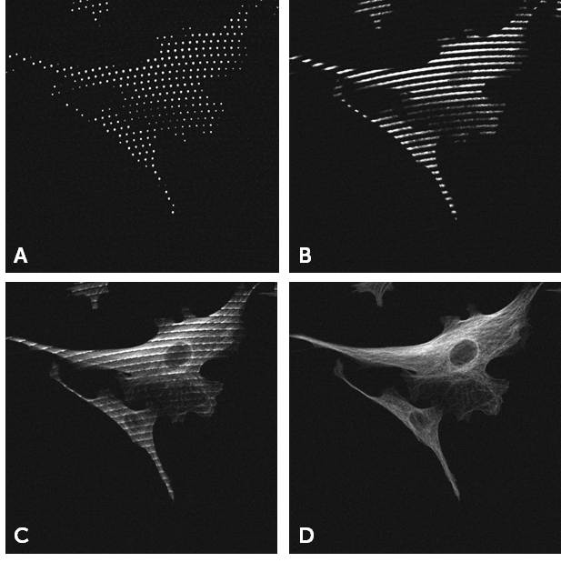
When capturing high-speed dynamic processes such as calcium imaging, short camera exposure times are necessary. These exposure times need to be as close as possible to the time taken for the disk to scan the image, in order to best capture high-speed processes. If exposure time less than the scan time, part of the image is not scanned and black lines streaks will appear on the image, as seen in Fig.7.

The solution to this problem at high acquisition speed is to synchronize the camera exposure to the scanning of the disk, ensuring that the exposure time is equal to a whole number multiple of the scan time. This requires both a high-speed camera and access to advanced triggering options, so that camera acquisition can be synchronized to the disk rotation. Photometrics sCMOS cameras feature both, with high speeds and access to hardware triggering.
The Kinetix sCMOS can achieve speeds up to 500 fps across the full 29.4 mm sensor, by cropping this sensor the speed increases linearly, easily achieving several thousand fps and matching to even the fastest SDCM systems. In addition, the Kinetix can also achieve over 100 fps in the high sensitivity low read noise CMS mode, allowing for a combination of high speed, large FOV, and high sensitivity. A high speed back-illuminated sCMOS camera allows for the full potential of SDCM systems to be utilized, especially if the disks can rotate at speeds of up to 15,000 rpm.
Simultaneous Multichannel Imaging
Many modern SDCM systems feature the ability to connect multiple cameras for two-channel detection or other multi-camera applications such as multi-focal imaging or imaging at different polarizations. In addition, certain techniques such as Förster Resonance Energy Transfer (FRET) can benefit from multiple cameras. The multiple cameras on a SDCM can be the same model of camera, for experimental consistency, or markedly different cameras. Cameras with different specifications could be used on a single SDCM system, allowing for the benefits of different FOVs, pixel sizes and magnifications on the same sample. By switching between cameras and objectives, vastly different experiments can be done on the same SDCM system with relative ease.
Future
With the massive steps that SDCM imaging systems have taken from the past to the present, how will these systems evolve in the future? Imaging technology advances alongside microscopy, and next-gen sCMOS models are already emerging in the form of the Kinetix sCMOS. The technology of the Kinetix can help to inform where imaging will be heading in the future.
Kinetix sCMOS: Go Larger, Go Faster
The Kinetix sCMOS is part of the next generation of sCMOS cameras, capable of imaging samples and allowing for experimental designs that may be impossible to capture with established technologies.
The Kinetix features extreme speeds, up to 500 fps across the full sensor, and easily reaching >1000 fps and higher when imaging across smaller frames. With a huge 29.4 mm diagonal FOV, the Kinetix also has a larger sensor size than most microscope systems can image, due to current sizes of filter cubes and camera mounts. This combination of speed and sensor size means that the Kinetix can easily outperform typical sCMOS devices, delivering over 4000 megapixels/second of data. Combining this with 95% QE, balanced 6.5 µm pixel size, and advanced triggering options, the Kinetix will push forwards the imaging industry.

Modifiable Pinhole Disks
As certain disk pinhole sizes are optimized for different camera pixel sizes, objective magnifications, disk speeds, and avoidance of crosstalk, the ability to change pinhole size or location on the fly would be extremely advantageous. The smaller the pinhole, the greater the maximum resolution of the system, but the more light is blocked. Combining smaller pinholes with low magnification, high numerical aperture lenses and a highly sensitive back‑illuminated sCMOS camera would allow for SDCM imaging across a large FOV without sacrificing resolution. Opening up the pinholes would then allow for more illumination and better contrast, at the cost of pinhole cross-talk, but these could be paired with optimal fluorescent probes to lessen the effect.
By having a SDCM system where disks can either be swapped out or a single disk can be modified, the ability to change both the pinhole diameter and pinhole spacing would allow for a great degree of experimental flexibility. Experimenting with other pinhole types such as slits or apertures would allow SDCM imaging to explore a wider range of experiments.
Deconvolution
While SDCM can produce high-resolution images, especially with super-resolution SDCM, this can be further increased by computational post-processing steps such as deconvolution. These steps can be time-consuming and computationally intensive, but more options will emerge in the future emerging for real-time deconvolution, both in the SDCM system and onboard modern sCMOS cameras. Several open‑source 3D deconvolution options are available for standard computers to run, allowing researchers to increase the maximum resolution of their system.
Other algorithms can be used to denoise images, lessening the effects of noise sources such as photon shot noise, which can impact the signal to noise ratio of imaging, but is difficult to deal with due to the random nature of photons.
Multiphoton Spinning Disk
As described in our two-photon microscopy application note, multiphoton imaging uses two or more near infrared (NIR) photons in order to image deep (up to several millimeters) into a 3D sample due to different absorption coefficients between visible light and IR. By pairing multiphoton imaging with SDCM, high speed imaging can be performed deep in living tissue, presenting a powerful platform when working with large model organisms.
However, it should be noted that multiphoton SDCM relies upon multiple pulsed infrared lasers across multiple pinholes, limiting the illumination area.
Summary
SDCMs have always had a useful role in life sciences, allowing for imaging of live 3D samples via optical sectioning. These imaging systems have significantly changed since their inception, increasing in FOV, resolution, and maximum imagins speed. All throughout this evolution, SDCM systems have been supported by a range of Photometrics scientific cameras, which have also greatly advanced in imaging ability over time.
By making changes to spinning disk pinholes, microlenses, and rotation speed, imaging with a SDCM can be flexible and change to your experimental needs. However, one of the best ways to evolve your SDCM imaging is using a modern back-illuminated sCMOS camera, which will benefit your imaging speed, resolution, sensitivity, and field of view, adapting to your sample and imaging requirements.
To find out more, refer to our Applications page on spinning disk confocal microscopy to find out the best cameras for this application, and how they can be demoed on your system.
References
Azuma, T. and Kei, T. (2017) Development of high-speed super-resolution confocal scanner. Yokogawa technical report English Edition. Vol 60(2) 33-37.
Oreopoulos, J., Berman, R., & Browne, M. (2014). Spinning-disk confocal microscopy. Quantitative Imaging in Cell Biology, 153–175. doi:10.1016/b978-0-12-420138-5.00009-4
Stehbens, S., Pemble, H., Murrow, L., & Wittmann, T. (2012). Imaging intracellular protein dynamics by spinning disk confocal microscopy. Methods in enzymology, 504, 293–313. https://doi.org/10.1016/B978-0-12-391857-4.00015-X